Mercedes-Benz Ponton 220S Sedan
Restoration Story / Part 4
by Terry Morgan / t_zmorgan@msn.com
Contents
-
Part 1 history
of the car / sub-frame removal / engine rebuilding
/ transmission rebuilding / front suspension rebuilding / brakes rebuilding
/ yet to do.
-
Part 2 engine rebuilding (oil pump, cylinder head) / transmission rebuilding
/ steering.
-
Part 3 engine compartment / front suspension / engine, drive train and
suspension installation / refurbishing heater boxes / reassembly of engine
compartment.
-
Part 4 engine compartment / heater boxes
(restored) / exhaust resonator / heater duct flaps / steering damper / brakes
/ rear axle / starting engine / rust repair / extra sound insulation /
suspension rebound stops / speedometer / cleaning fuel lines / fender straightening.
This is the story of the restoration of my 1959 220S sedan up through March 2001.
Engine Compartment
After installing the engine, (See part
3 of the story) I moved the car into my new shop and finished installing
all the engine compartment components. I forgot to replace the rubber
seals that go under the middle of the heater boxes and up the side of
the inner fender, so I got to remove the heater boxes again. The parts
place doesn't list new rubber seals. They said they are from "bulk material."
Mine were cast and though I would like new ones, they cleaned up adequately
to re-use.
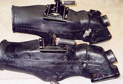
Reconditioned heater boxes before installation
Exhaust Resonator
The donut gaskets on the header pipes
were pretty well bonded/rusted onto the pipes. They contain laminated thin
metal throughout that rusted and bonded onto the pipe. I had to chisel
the things apart, then use a chisel and tiny punch to clean out the crevice
where the gasket seals.
The "muffler" on the exhaust manifold was dented
and had some holes at the bottom end, though the pipes were sound. I checked
at a local muffler shop for something that could be retrofitted, but it
would be a bunch of trouble because of the two pipes coming in at one end.
Though it was probably possible to weld something up, I decided to see if
mine was repairable. Using a tiny cut-off wheel, I removed the outer metal
cover by cutting along the base of the pinch welds. I carefully removed the
asbestos insulation pieces. I set these aside where the fibers would not
be disturbed.
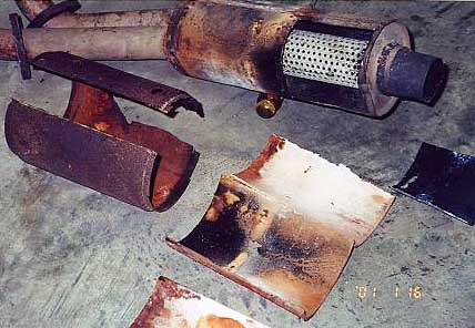
Resonator after cutting open, showing removed
cover piece and asbestos insulation
Using an air cut-off wheel, I cut out the rusted
and dented part of the resonator and sandblasted the inside and outside.
After sandblasting, I could even read the original supplier's name and part
number. It is interesting that it is divided into two halves internally.
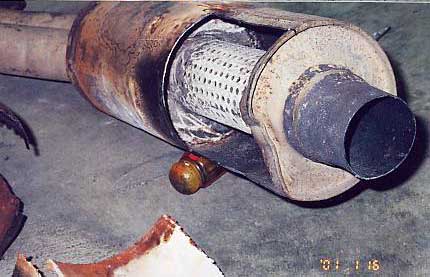
Inside of resonator, before sandblasting
The top half is simply an open chamber where
the two pipes come in.
From body repair sheet metal, I fabricated
a new replacement piece and took it to a car restorer who welded it in.
I painted the whole thing with the high temperature silver paint from POR-15.
This paint "cures" at 350 degrees, so I cooked it in the oven. Don't do
this in your food oven unless you live alone and don't mind the very strong
chemical smell that will stink up the whole house. Though this paint will
rub off and marks easily before it is cured, it is very tough after curing.
I got some thin galvanized sheet metal and
fabricated a new outer cover piece. It was tricky to form the stepped ends.
I made a kind of form from metal strips and a hose clamp around a piece of
6" PVC pipe, then crimped the ends down over the "form" with pliers. I cleaned
the asbestos insulation (very carefully, outside, wearing a mask) and painted
it with the high temperature paint to prevent further fiber disintegration.
I had the same welder tack the cover together and to the resonator.
I used a piece of coat hanger wire to measure
the angles and length needed for a piece to connect the resonator to the
remains of my exhaust system. I took it to a local muffler shop where they
graciously made a connecting piece for free (though it took 3 tries and two
trips) and I promised to drive the car to them later for a whole replacement
system.
Heater Duct Flaps
After painting the ducts, I installed the air
flaps. I used some foam from those cheap foam paint brushes to replace the
foam seals on the flaps.
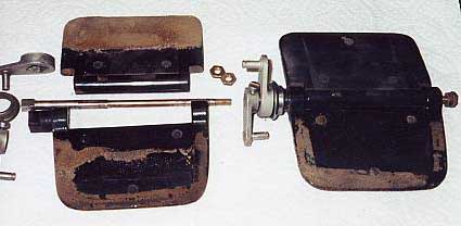
Heater duct flaps (after cleaning but before
the foam was glued on) and parts
Steering Damper
Jack Kotrba (thanks, Jack!) sent me
a used steering damper and I cut it open. As I suspected, they are not
designed to be rebuilt (well, I was hoping). It is possible to remove just
the ball joint end (in case it is kaput, but the damper is OK, remove the
crud around the narrow neck and drive out the small roll pin, then unscrew).
At the piston end, the metal case is machine rolled into a groove in the
aluminum end piece, so some careful cutting of the edge of this groove (using
a tiny cut-off wheel on a Dremel tool) will release it. Some good epoxy might
hold it back together, but without new seals and the correct replacement
oil, it's just an academic exercise. So I need to buy one or find a decent
used one.
I have heard a rumor that is it possible to use
a later damper (for a sixties MB that cost about $25) that has the "eye"
end at both ends. A special bolt adapts the eye end to the hole in the pitman
arm.
Brakes
I used the same front shoes but replaced
the rear brake shoes because they were oily and mostly worn out. I put new
adjuster friction washers on the rears - it was a bit of trouble to get
them loosened without the special wrench, but I managed to use a combination
of vice and open wrench to do it. Luckily, none were seized.
On each backing plate is a small aluminum
housing containing a pulley where the parking brake cable goes in, and cleaning
off the 40 year's worth of petrified dirt and grease reveals a nice aluminum
housing. I had to re-set the cable adjustment at the equalizing lever (right
above the drive shaft at the differential) to get enough slack in the parking
cable to allow me to connect the lever under the hood (I found out later
why the cable seemed so short - see the section below on first drive). That
was messy also, but it was an opportunity to remove and clean these parts
to like-new condition.
If you only need the rubber seals and don't
need the hard parts for your wheel cylinders, you can get replacement rubber
seals from any parts store that carries brake kits for American cars. Mercedes'
suppliers used inch sizes on the bores and seals, like most (all?) other
manufacturers. Just look at the size written on the seal and ask the parts
guy to look up something that uses that size (15/16"). My replacement seals
were for a mid-sixties Chevy and cost about $3.00 for each corner. Note on
the seals: there are two basic designs: with and without an "expander" piece
to help expand the seal against the bore. If the new seals don't come with
expanders (as did the originals), don't use the old expanders and instead
use the custom springs that come with the new seals.
I replaced the rear flex hoses without any
grief. The fronts also came off easily, but they had been removed around 1980.
I bled the brakes with my vacuum pump system,
but there was still some air somewhere. Got my wife to help do it conventionally
and the air was in the fronts.
Rear Axle Bearings and Seals
I removed both rear axles to replace
the two seals around the bearing on each side. To get the axles off, you
need to remove the brakes, remove the 6 to 8 (?) small bolts that attach
the bearing retainer plate and brake backing plate, and then tap out the
axle with a slide hammer. It came out very easily (though it's a little messy).
Getting the bearings off the axle took some doing - I took them to a friend
who has a press and it took significant rigging with spacers, blocks, angle
metal, etc., to rig it properly to push the bearing off. The bearings must
come off to replace the outer seal (in the retaining plate). The right bearing
had been noisy since I bought the car. Sure enough, it was badly pitted.
Miller's MB supplied the new bearing, locking washers for the bearing retaining
nut, inner and outer seals, and paper gasket (these parts are relatively cheap).
Getting the inner seal installed in the axle
tube was also a bit of trouble without the special tool. If you replace this,
have someone with a lathe make you a proper tool to drive it into place -
it will be worth it. Use a thin coat of silicone sealant around the outside
edges.
For installing the outer seal into the retaining
plate, I made a "press" with some small plates of metal and used my vice
to press the seal into place. This way it gets pressed in squarely and doesn't
damage the seal. I used the old seal to press it the final few millimeters.
Then, while installing the axle, I discovered that
I installed one of the bearing retaining plates (and the seal in it) backwards
and had to do one axle all over again! Well, it sure LOOKS like it should
go the other way. :-(
Engine Start
Before I set the timing, I fabricated
a rod that fit down into the distributor hole and engaged the oil pump.
I spun this with a drill to prime the oil galleries. This worked well except
for a spill where I had loosened the fuel pump so its plunger would not
be activated (this made it easier to spin the pump). Surprisingly, this
place gets well flooded with oil and I had to mop up about a half quart
of oil.
The gas tank is not yet installed, so I
used an oil bottle for gas and a line to the fuel pump. I held a rag around
the top of the bottle and pressurized the bottle with an air nozzle to force
gas through the pump and into the carbs. This primes the pump and saves
the starter.
I statically set the timing and checked
all the wiring. New battery, hooked it up, looked for sparking on connection;
OK. Tried the starter for a second; OK. Checked for gas at the carbs; OK.
Checked for accelerator pumps squirting; NOT OK. So removed the accelerator
pump diaphragms and cleaned; about two hours of fiddling around and cleaning.
Reinstalled; OK. Tried the starter and instant vroom! Nice! No strange noises,
no leaks; OK. After a minute or so it even idled on its own. Ran it until
it fully warmed up, then shut it off.
The next running was a few weeks later when I drove
it up and down the street a few times. No front fenders yet, so no lights;
no gas tank so can't go far anyway! Brakes work OK, stops straight. Some
noises from drive line when coasting; later investigation on my lift showed
the parking brake cable was wrapped once around the drive shaft, so I had
to take the lever off to unwrap it from the front half of the shaft. If that's
all I did wrong, I consider that good!
Rust Repair
After cutting away all the badly rusted
metal at the bottom of the front door posts, I got some 16 gauge body sheet
metal repair stock and then cut and shaped metal pieces to fit. The required
trial and error is rather tedious, which is why rust repair can quickly
run up big $$ -- good thing I work for free. A restorer friend will bring
his welder to weld these pieces in before I replace the fenders.
Jack also sent me new door hinge screws
and a new screw plate. I had to drill out several of the rusted screws.
I added an "x" brace to the radiator frame.
I had long noticed that the whole front end would shake side to side on
severe bumps, and I noticed that Kevin Clemens added the same kind of brace
to his "Around-the-World" rallye car. I got some screen door adjusting rods,
cut them and beveled the ends, and made a small depression where they will
be tack welded to the lower front cross member in front of the radiator.
The spot welds to the right side of the
inner fender are partly rusted and partly just broken, so those will be
re-tacked by my welder.
Extra Sound Insulation
I put foil lined jute sound insulation
on the bottom of the floor boards, under the rear seat, behind the stock
cardboard panels below the windshield, and behind the driver and passenger
side kick panels. I got the stuff from an upholstery shop and they gave
me some glue for it also. I will get another piece for the underside of the
hood. When I take the door panels off, I plan to put some on the inside of
the doors.
Foam Sound Deadening
The car originally had sheet foam glued to
the back of the metal panels above the firewall. I found an upholstery
trim shop that had some gray foam with cheesecloth backing that is a reasonable
replacement. They also sold me a spray-on contact adhesive that made it
very easy to apply the glue.
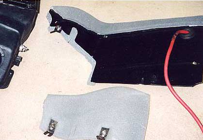
Foam insulation on firewall pieces
Kick Panels
The cardboard panels on the sides of
the front foot wells were damaged by moisture that entered through the rusted
out areas behind the wheels. You can get cardboard replacement stock but
it is not the original color or texture. I got some vinyl of the proper color
and I plan to wet the bottom of the panels (the only area they are deformed),
mold them back to a flatter shape, and glue on the vinyl.
Suspension Rebound Stops
I got new rubber front suspension droop
stops, but not before the suspension was assembled and installed. Putting
these in is a pain - do it before installing the upper A-arms. I jacked
up the car so the upper a-arm would help push the tab through (with a little
grease on it), but I had to use a string under it to pull on the side that
didn't start through, and, while working upside down, try to pry the rubber
so it would come out through the hole, all the while adjusting the jack
for more or less pressure on the top. Good thing the fenders are not in
the way!
Speedometer
Once in the past, my speedometer filled with
grease and indicated many times higher than it should. The grease was pumped
up the drive cable (like an Archimedes screw) and filled the drive mechanism.
The drag on the grease is like a viscous drive coupling (normally, there
is air between the spinning magnetic disk and the driven cylinder) and makes
the speedometer read very high - it pegs out when going only about 20 to
30 mph, depending on temperature. It had happened again just before I disassembled
the car. The inside of the speedometer is a fine piece of craftsmanship
and assembled like a fine instrument.
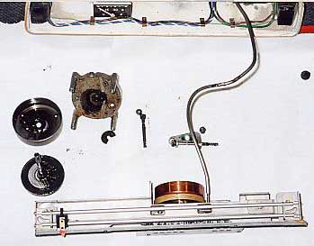
Speedometer pieces after disassembly
and before cleaning. Disk (lower left) shows grease that got inside, half
wiped off. Cylinder for disk above, with grease inside. Die-cast drive
piece to right. Cable is for odometer reset. Small gears are for odometer
drive.
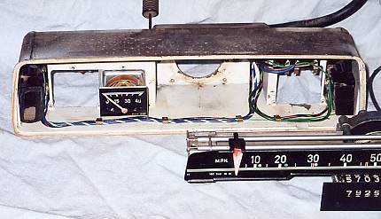
Front of speedometer case
The indicator needle is moved by a VERY thin wire (about the
thickness of a human hair) that is wrapped around a spiral-grooved drum
that is driven by the spinning input disk. Pulleys at each end guide the
wire around the ends of the scale where the guide rods for the indicator
needle are attached.
Back of speedometer mechanism, gauge mask,
gas gauge, and lamps
To Disassemble the Speedometer
- Remove the speedometer unit from
the dash. Despite what the manual says, you don't need to totally remove
the temperature gauge capillary tube from the car; you only need enough
slack to be able to remove the 3 screws on the back that attach the
temperature gauge (though it's a little difficult working backwards
and blind while trying not to scratch the dash or steering column).
- Carefully pry the chrome surround
off the case, starting at one end. It doesn't need to be bent significantly
to remove it, but having three hands helps.
- Remove the glass. It's held with
sticky tape so it may take a small suction cup to get a grip on it.
Remove the mask for the scales.
- Remove the four screws in the
back that attach the speedometer drive mechanism and remove the speedometer
and mechanism with scale.
- Remove the screws in the back
that hold the drive mechanism on. Watch for washers and spacers, especially
the very tiny washer on the pin that centers the driven cylinder on
the spiral drum.
- There is a thin metal washer
and a thin rubber washer sandwiched behind the die-cast piece (that
holds the shaft of the spinning disk, where the speedometer cable
attaches) and the cylinder that houses the spinning disk. I think
the rubber seal is supposed to keep any oil or grease from getting
past, and there is a groove on the back of the cast piece that will
let the fluid out to the side. To repair the worn rubber washer, I
put some silicone sealant on it when I reassembled.
- Behind the odometer scale on
the left side, under one of the screws, is a piece of metal that acts
as a stop for the return spring. When reassembling, adjust this so
the needle rests exactly on zero.
- Use a soft camera lens cleaning
brush to clean the scales and other parts.
- One of the pulleys is mounted
on a separate piece that allows adjustment of the tension on the wire.
There is a tiny tension spring at one end of the wire where it attaches
to the indicator needle. This spring was completely slack, so I loosened
the screw and moved the pulley outwards a little to take up the slack.
- The speedometer is calibrated
via an adjustment nut (located behind the scale and below the spiral
drum) that adjusts the tension on the main spring that returns the
needle to zero. If you have a way to accurately spin the input shaft
so the odometer increments one mile every 60 seconds, you can adjust
the tension spring so the needle reads 60 mph (1 mile/minute). (I did
not try this and I suggest you use a speedo repair shop.) You cannot
"calibrate" the odometer because it is direct drive at a fixed ratio. If
you need to calibrate your odometer and speedometer to your car because
you have tires of a different diameter than stock, you need a small
gearbox that connects between the transmission and the speedo cable
to change the overall ratio. These used to be available in various ratios.
- My sandblasting of the engine compartment
managed to get some sand inside the speedometer case (I'm sure I'll
be finding sand in strange places for years to come?). There are holes
in the tiny rivets along the bottom that hold the clips for the wiring,
and gaps around the holders for the indicator lights. I these filled
these openings with little dabs of caulking.

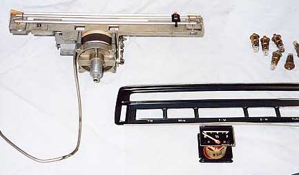
Back of speedometer housing and instrument,
before reassembly. Adjustable pulley end for tensioning the wire is visible
on left end of speedometer mechanism
Cleaning the Fuel Lines
The fuel lines had lots of "varnish"
from ancient dried-up fuel. To clean out the lines, you can use spray carb
cleaner or lacquer thinner (paint thinner won't cut it). I took the fuel
filter out of the reserve selector and put the end of the hose into a beer
can to catch the fluid. I sprayed carb cleaner into the rear end of the line,
using a rag to seal the spray tube around the line. If you use lacquer thinner,
you can run a hose from the fuel line into the bottle and use compressed air
to carefully pressurize the bottle to push the fluid into the line. Then blow
out the line thoroughly. Warning: if your fuel selector is still installed
in the engine compartment, one of the lines is not open at that end (depending
on the position of the selector) - if you pressurize this closed line, the
fluid will shoot back out into your face when you release the pressure! You
DO NOT want to get this stuff in your eyes!
Fender Straightening
Using a come-along, I hope to straighten
the inner fenders that are a little bowed out from the collision the car
had at some point in its early history. I had always noticed that the front
fenders seemed to bow outward over the wheel openings more than they should.
When I put the hood on without the fenders, I could see that the top edges
of the inner fenders were not parallel with the sides of the hood. I'll describe
how this goes in a future installment.
Created: April 16, 2001
© www.mbzponton.org
Return to the Ponton Workshop page