Chris Williams / Marion, New York / 1958 Type 220S sedan
Hydrak Reviews
Reviews of the Hydrak clutch option are, as the saying goes, "mixed." On one hand, it truly is an engineering marvel, and there is some well deserved pride in being able to keep a Hydrak system functioning as designed. On the other hand, it seems like an overly complex mechanism, which is failure prone with several points of vulnerability, and consequences of such failures can be expensive. The debate, as to whether (or not) to convert a Hydrak car back to a conventional clutch arrangement will certainly continue on. As someone who's had a working Hydrak, and done the conversion back to three pedals, I thought I'd share my rationale and some observations gained during the process.
Backstory
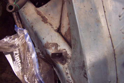
A little background may be in order. My car, chassis number 220S-011 7506819, was sold by Studebaker-Packard as a 1958 model year but completed in August 1957. According to the Data Card, the car was completed with a conventional clutch, but shipped to the USA with a Hydrak Conversion Kit, and subsequently converted here in the US prior to sale. In the engine compartment, there is evidence that the bracket for the fuel filter and selector valve was relocated a bit forward to make room for the Hydrak servo. The original location is visible in Photo 1, taken during an engine compartment "freshen up" in 2015. Although not the easiest to see in the picture, the installation at the new position would definitely qualify as a "field weld."
Photo 1. Fuel filter bracket in the engine compartment.
The car was purchased by my father as a used car in 1961 from a third party, brokered through Martin Loeber Motors in Chicago, and as far we knew at the time, the Hydrak was original equipment. As a result, when offered a conversion in the mid to later '60s, my dad elected not to, in the interests of keeping the car original. It was only after obtaining the Data Card from the Classic Center many years later, and discovering the earlier location of the bracket, that I realized that "original" was a conventional clutch.
I suppose that was one motivating factor for my decision to undertake the conversion, but there were several others. I'd never been happy with the clutch engagement when stopped. Even when "new to us," the car always lurched a bit and hunkered down on the front springs when engaging the clutch at a dead stop. Additionally, the requirement to be absolutely correct when matching road speed and engine speed in gear was somewhat problematic in achieving a smooth shift, and I felt I could do better (most of the time) with a conventional clutch arrangement.
Another factor motivating the conversion was learning the hard way what some of the potential failure modes could be, and their impacts. One that we "tested" when the car was fairly new to us was the breakage of the small wire that runs up the shift linkage to the "clutch switch" on the shift lever. If that wire breaks and the end shorts to ground, the clutch disengages and will not engage until the wiring at the control valve is disconnected or the wire is repaired. Another failure, more insidious, is that if the control valve is leaking, i.e. applying some vacuum to the servo without discreet shifting action by the driver, the effect is to ride the clutch. This mode passes the "could be expensive" test. In my case, that led to a need to regrind the crankshaft main bearing journals and in particular the thrust control surfaces at the number 2 main journal. New main bearings, of course. Photo 2 shows the damage to the original bearing shells. Note the difference in thickness on one side of each of the shells. The giveaway clue to this occurrence was excessive end play in the crankshaft.
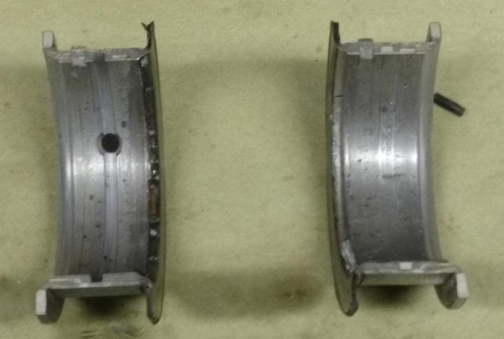
Photo 2. Damage to the bearing shells.
Technical Geek-Out
Another consideration is that the release or throw-out bearing in a Hydrak system is a carbon pad, whereas the conventional setup uses a rotating thrust bearing. Given what I now knew, and in particular the knowledge that the Hydrak system could ride the clutch without any symptoms I could detect, I became convinced that a "reconversion" back to a standard clutch was an important step in the preservation of the car. Henry Magno (see Links page), who oversaw the repairs to the crankshaft and the reassembly of the engine, helped me arrive at the decision by supplying the necessary parts and encouragement to make the leap.
The conversion process is fairly comprehensive. Henry oversaw the crankshaft repair, replacement of the flywheel and the installation of the clutch assembly itself. He also had the crankshaft, clutch and flywheel assembly balanced. I picked up the completed and assembled engine at Henry's shop, about a seven hour drive from home, and added a replacement front drive shaft section, a new bell-housing, pedals, and all the little parts, clips, springs and shafts necessary to hook it all together, along with another transmission with the correct input shaft.
In principle, the fluid drive and the associated and very heavy flywheel come out. That allows a shorter bell-housing to be used, which in turn moves the transmission forward. Then, of course, the transmission input shaft needs to be shorter, not only because of the new placement, but also due to the removal of the fluid drive, and then the driveshaft needs to be longer. Additionally, the shift rods to the transmission need to shorten up as well. The bell-housing on the left (Photo 3) is for the Hydrak installation, and the one on the right is the standard unit.
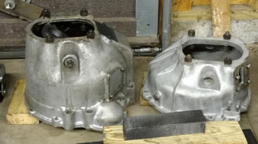
Photo 3.
Onward!
The most practical way to get at the Hydrak bell-housing and transmission is to simply drop the front sub-frame out of the car. I used the gantry I'd built for the 2015 "freshen up," along with the two chain falls and pin blocks to lift the car off the sub-frame once everything had been disconnected. Yes, the radiator needs to come out and the fan should come off to allow sufficient clearance at the front of the engine compartment as the car is lifted off the sub-frame in this manner. The bonnet or hood should also come off to grant easier access to the shift linkage, oil pressure hose, etc. I used a pair of wheel dollies under the front wheels to make positioning the engine and sub-frame that much easier when reassembling. `At the rear, I did build the "tail wheel" assembly noted elsewhere on this site, and used it during the 2015 freshen up. After that, I found that a simple rolling floor jack was an acceptable substitute.
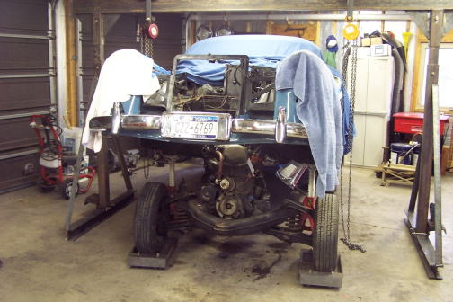
Photo 4. Lift the car off the sub-frame.
For Functional Clarity
I mentioned the need to replace the transmission input shaft due to the need to change its length. Photo 5 shows the difference.
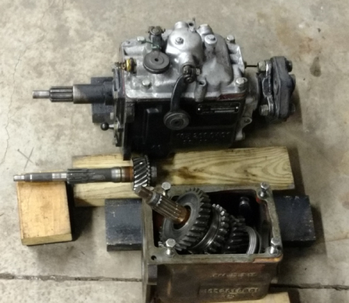
Photo 5. Transmission input shaft length comparison.
Are We There Yet?
Henry had provided a replacement transmission with the correct shaft. My father had replaced the transmission in our car not many miles before the car went into prolonged layup, and in comparing the two transmissions we elected to replace the input shaft and front plate on the transmission that had come out of the car, the one installed as a replacement. I'm indebted to my good friend Ben Jacob at British Auto Salvage in Walworth, NY, who's a good transmission guy. As a side note, the balls in the front bearing were not, at least in our case, encapsulated in a race. They need to be retained with "tacky grease" during assembly, and, as we tested, they may fall out of the bearing during disassembly. I suppose it's possible that some day we'll find the remainder of those balls that hit the floor, but in light of that experience I recommend pulling the input shaft over a catch pan or basin "just in case." We cannibalized the necessary balls from the transmission Henry's had provided and pressed on. We saw no visible wear marks on the balls we used, which matched the balls we had.
It was a similar story with the driveshaft. We needed to "stretch" the front section, but the center bearing and rubber parts on my shaft were in better shape, and the shaft condition was better overall, so we used mine. I had a drive line specialist shop, Fleet Pride, in Rochester, NY do the work, by welding in an additional section of tubing in my shaft.
While the engine and sub-frame were out of the car, I was able to remove and replace the single, large brake pedal with the smaller size, add the clutch pedal and shaft, and install the linkage for the clutch release. The Ponton clutch release linkage is purely mechanical, so there are some bits to assemble under the car to make this work. Using parts provided by Henry, and some pictures I had taken at Henry's shop, I was able to get this in place without much of a struggle. Photo 6, taken of a 220SE in Henry's shop while I was picking up the engine, shows the clutch linkage from the left side of the car, with the pedal return spring to the left, the actual release lever inside the turnbuckle-like frame in between the adjustment screws, and the shaft from the clutch pedal in the upper right hand corner.
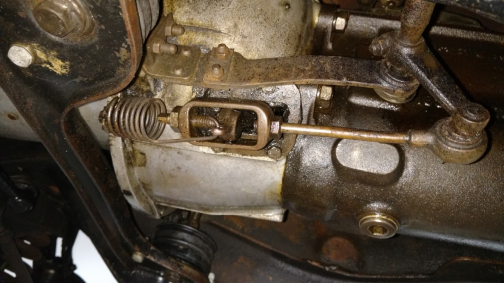
Photo 6. Clutch linkage in a 220SE seen from left side of car.
No Pain - No Gain
Also while I had the body up on stands at the front, I removed the Hydrak vacuum reservoir and associated hoses. I also took a little extra time to do some preservation in the space where the reservoir had been. Back in the engine compartment, I replaced the three way vacuum fitting on the brake booster with a two-way that Henry had provided, eliminating the connection for the vacuum reservoir.
Probably the biggest challenge I faced was removing and reinstalling the driveshaft. The bolts securing the center bearing need to come out, of course, and then the entire assembly can be carefully slid backwards and out of the car. It goes back in the same way. It would be far easier to do this if the differential and rear axle were out of the car. It can be done without removing the rear axle, but it's more of a struggle. It might have been easier with a helper, but it can be done working alone - just a little more time consuming. It's also very important to make sure the universal joints in the driveshaft are aligned correctly. There are marks on the shaft and on the sleeve, which holds the front flange. As much as it would have been easier to reinstall the driveshaft with the front flange removed, I elected to do it with the front flange installed, to ensure the alignment was correct. It did increase the "fun factor" considerably. Photo 7 shows the alignment marks, plus a paint mark I added for double verification.
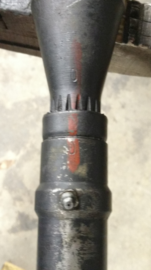
Photo 7. Drive shaft alignment marks.
Time For A Cold Beverage
With the driveshaft back in the car, we lifted it again, rolled the engine, transmission and sub-frame back into place, carefully lowered the car onto the sub-frame and reconnected everything, using the shorter shift rods that Henry had provided.
I'm certain my opinion is biased, but I'm extremely happy with the result. The intended endpoint for my car is to be a car that is driven. It looks nice, and it's well preserved, but it won't be a "trailer queen." Going back to a conventional clutch was, in my opinion, well worth it.