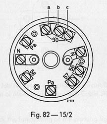
Figure 82-15/2. Service Manual Model 190 (SM-1207-000)
Rotary light switch terminals (for headlights and
more)
view Benedito J. T. Rodrigues' Rotary Light Switch article
Back in 1995 when I restored my 1961 Mercedes-Benz Type W120 180b Ponton sedan, the electrician had to replace the original rotary light switch with one from a Mercedes-Benz W123 chassis. After making this repair, the electrician did not connect the wires in the correct manner and this resulted in the following faults.
- The rear clearance lights (European specification, part of the tail-light cluster) did not function at all
- When the headlights were turned on, the front clearance lights (part of the side blinker cluster) also turned on
I decided a long time ago to repair this defect. However; I always thought that it would be a major problem and that it was beyond my capabilities. Finally, two days ago I located three original used rotary light switches in very good condition and decided that it was time to fix this long-standing fault. Before doing anything, I spent some time studying the components of the electrical system. With the help of the electrical diagram in the Owner's Manual I was able to figure out that the role of the rotary light switch is by far more important than I thought. Apart from being the switch used to turn on the parking lights, tail lights, instrument light, high and low beam, fog lights and clearance lights it is also the base for many connections such as the interior dome light, the electric clock and an additional electric socket that is used for an option such as a radio.
Figure 82-15/2. Service Manual Model 190 (SM-1207-000)
Rotary light switch terminals (for headlights and
more)
According to the electrical diagram in the Owner's Manual, the rotary switch has the following numbers and letters on its terminals: 30, 56, 57, and 58, Pa, PaR, PaL, N, and N. Each terminal is connected to one or many components of the electrical system of the car. However, it is difficult to determine the connections based solely on the diagram. Therefore, I consulted the Service Manual Model 190 (SM-1207-000) (concise edition) to figure out clearly where each wire goes. Reference: Job 15/2 in the Manual.
According to the Service Manual terminal 30 has the following connections...a) A thick red wire (cross section 4mm²) coming from the starter.
b) A red wire (cross section 2.5mm²) going to the ignition lock.
c) A red wire (cross section 1mm²) going to the fuse box and connected to fuse number 1 (electric clock, extra socket, dome light, clearance lights).
As for the terminal 56, it has the following connection...a) A white (coded with black) wire (cross section 2.5mm²) going to the low/high beam foot switch. (Note: In the 180b the wire is just white there is no black coding)
As for the terminal 57, it has no wires connected to it.
For the terminal 58, it has the following connections...a) A gray wire (cross section 1mm²) going to fuse number 8 (tail light and headlight parking bulb left). Note: In my 1961 Type W120 180b, there are two gray wires; one of them is coded with black. The gray one goes to fuse 8 and the other goes to fuse 7. The Service Manual indicates that the connection between the two fuses is made in the fuse box while the connection is in the rotary switch at this terminal in my 180b.
For the terminal Pa, the following connections exist...a) A red wire (cross section 0.5mm²) coming from fuse number 1.
b) A red wire (cross section 0.5mm²) going to the roof light door switch.
For the terminal PaR, the following connections are made...a) 2 green wires (cross section 0.5mm² each) one going to the front right clearance light and the other going to the rear right clearance light.
For the terminal PaL, the following connections are made...a) 2 green wires (coded with black) (cross section 0.5mm² each) one going to the front left clearance light and the other going to the rear left clearance light.
The two remaining terminals (N and N) are for the fog lights.
To one of the Ns a grey wire (coded with red) (cross section 2.5mm²) coming from fuse 8 and to the other a black wire (cross section 2.5mm²) going to the fog lights.
These are the connections at the rotary light switch of the b and c models. The previous ones had a separate switch for the clearance lights. The principle is the same, the connections at the PaR and the PaL go to the separate switch and a wire connects it to the Pa terminal of the rotary switch.
According to my belief, the wiring system is very simple and straightforward once the wiring diagram and the color codes are available. The rotary light switch plays the role of a hub to the electrical system since the positive cable coming from the battery/starter goes directly to it and from there the current is distributed to the entire electric system.- Ramzi Saba / July 6, 2005
Created: July 6, 2005 / Jeff Miller
© www.mbzponton.org