Anthony Tugwell / AnthonyT@Mail.com / South Australia
Introduction
I am pleased to provide a bit of extra information about my carburetor reconditioning, just completed. I have tried specifically to add to the other articles already included on the Ponton Workshop page. Both Jack Kotrba and Gordon Lewis have offered good advice, so what I have tried to do here is enhance these articles, provide a lot of photographs and add, hopefully in a useful way, to the overall understanding of the Solex Type 32 PAITA carburetor.
As with all such "advice" it is presented as personal experience and might not necessarily cover your car. This article is targeted at the Mercedes-Benz Type W180 II 220S Ponton sedan with the twin Solex "PAITA" carbureted, "M 180.924" engine. This model was sold from 3/56 to 8/59. It will also be appropriate for the carbureted coupé and soft-top (cabriolet) versions of the car, from approximately the same period. If you have a Mercedes-Benz Type W180 I 220a Ponton sedan (6/54-4/56) with a single Solex PAITA carbureted "M 180.921" engine, this article will also be of use.
Refer to my photographs while you read this article. Refer also to the Mercedes-Benz exploded parts diagram of the Type 32 PAITA carburetor, which has all items numbered. I use those numbers below.
Larger Image / Item Descriptions
Notes
The Type 32 PAITA carburetor diagram is included in the following Mercedes-Benz factory literature
Mercedes-Benz Type 190 Spare Parts List / Edition A / May 1956
Table 5 / "Carburettor" / Type 32 PAITA / Page 32Service Manual Model 190 (SM-1207-000)
"Component Parts of Compound Carburetor Type 32 PAITA"
07-0/14 (Job Number 07-0, Page 14)
In certain documentation (e.g. Mercedes-Benz Type 190 Spare Parts List Edition A / May 1956) the Type 32 PAITA carburetor is referred to as Type 32 PAJTA. The letter "I" (in PAITA) is substituted with the letter "J." For details, see the Technical Data Gasoline Models page.
Parts Kit
Through the International Ponton Owners Group (IPOG) discussion list I bought two carburetor reconditioning kits from Doug Broome. These were "Royze" kits SO-10K and included all essential parts. By this I mean gaskets for all jets, (including some spares), gaskets between carburetor major parts, and between carburetor and engine. Also included were a new idling jet, a new fuel inlet needle valve, and diaphragm and gaskets for accelerator pump and starter air valve.
As is the case in other situations, beware of original equipment (OEM) parts, which might include "new" but actually aged rubber parts, for example, diaphragms. If you are a true purist, the issue of originality could override the ageing of rubber compounds. In my view it is of no use having (for example) 50 year old 1956 diaphragms in the original rubber material, because these may well fail very quickly in service.
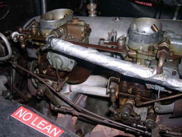
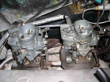
Carburetors in place on the engine before removal
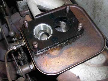
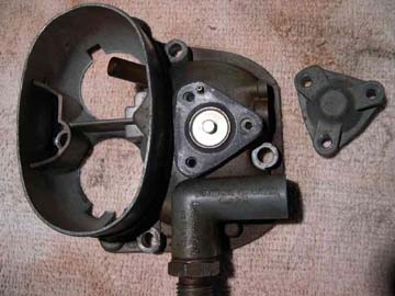
Original mounting block and drip plate — gaskets were both missing
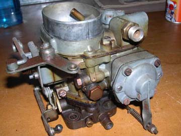
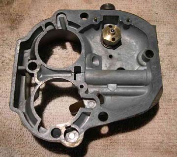
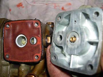
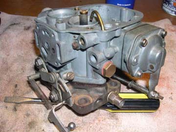
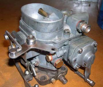
Front Solex Type 32 PAITA carburetor on the bench
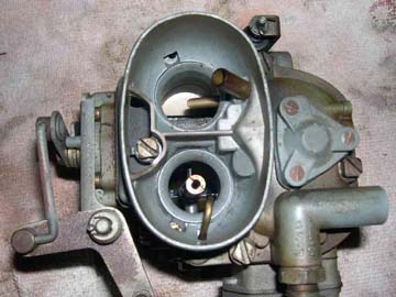
Top view of carb during disassembly
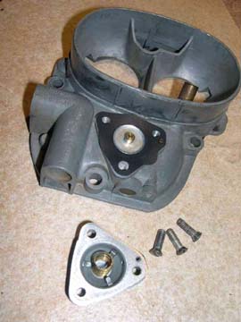
Carb top #151 removed
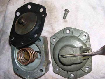
Note triangular starter air valve diaphragm #168 (#166 cover removed)
Underside of carb top showing fuel inlet needle valve #156 (brass)
Top view of carb, top section removed
Note float #52 & float chamber with fuel still inside
Accelerator pump separated; rear of rear section #92, orange gasket #108
Pump items: front cover #91, front of rear section #92, spring #94, plate valve #95, diaphragm #93
Disassembly
Jack Kotrba covers disassembly in an accurate manner. However it is invaluable to take lots of your own photos during disassembly. The advent of the digital camera is, of course, a boon here.
It is useful to mention the following variations or alterations to other information, which came up in my particular case, as well as some suggestions:
Thanks to Doug Broome, my reconditioning kit included the fuel inlet needle valve diaphragm. It seems that some other kits do not have this item.
Get hold of a couple of multi-compartment boxes to put all the carburetor parts in when disassembling. Putting them in order helps reassembly.
I did not see the need to remove the butterfly assembly. As Jack has noted, disassembly should only extend as far as reasonably necessary. I was able to clean all parts, butterfly parts, bushings and the like and so left this section of each carb in place. You should however check for excessive movement in the butterfly bushings, in which case further disassembly might be required.
My "Glenn's Repair and Tune-Up Guide" refers to a little ball in the primary emulsion tube, under the jet. Both my carbs had no little balls. They did however have brazed semi-circular ends to these jets. I think there has been a design change here since I carefully measured the clearance between the jet and tube and there is no chance of an extra ball fitting inside this emulsion tube. Jack and others also do not mention little balls!
I noted that a previous owner had failed at some point to install gaskets between carburetors and their engine mounting plates. This immediately explained the significant fuel loss I was having around the base of each carburetor on my car.
Clean Up
Clean up everything with a suitable cleaner. I used carburetor cleaner from a spray can which worked quite well. However there are all sorts of little nooks and crannies inside and around the main body of the carbs that need a lot of work; cotton buds and more carb cleaner will suffice.
Do not skimp on this phase of your work! Rinse with more cleaner and/or blow clean.
The following are recommended as desirable. They are not strictly necessary but seem sensible where you are rebuilding an item which might have been in service for 50 years.
Carefully tap the main threads to carb top screws 196; jet locations where you can get access, eg for 66, 68a, 71; also for fuel inlet 161.
Also clean up, with a die but using great care, the screws/jets which fit into the above locations, but avoid removing metal. By doing steps 1 & 2 you are removing the corrosion of possibly 50 years.
Carefully clean up the exteriors, bolt flats and the like of jets, bolts, fuel fittings, alloy parts etc. etc. I used a fine wet/dry emery paper for bolt and jet faces; on levers, alloy parts and other contoured items. I used a foam rubber sanding block of wet/dry paper which worked extremely well and was long-lasting.
Faces of mating parts, accelerator pump, top of carb and the like should be buffed up on a flat plate or block using the above wet/dry paper.
Clean up and check operation of control levers to accelerator pump, rotary slide valve and choke. Align levers and correct any bending which might be present.
Clean up the four mounting studs on the manifold which bolt down each carburetor. As also described above use a suitable thread die and clean up the accumulated corrosion, general grime and rubbish but do not start removing metal.
Because the carburetor body is made of alloy I saw that corrosion, albeit slight, was evident all over, and it was for this reason that I did the above things. It certainly made reassembly a lot easier and I suspect that all bolts and fixings tightened up far better. (I have seen a couple of reports of later re-tightening being needed). You must of course, because the metal is somewhat soft, be careful to not get a thread crossed or over-force a tap or die.
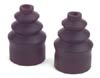
I was able to "create" new rubber bellows for the dashpot shock absorber. My originals were completely hard and irretrievable, so acting on tips on the International Ponton Owners Group (IPOG) discussion list about using model aircraft/boat etc. parts I looked for and found a suitable item.
The item I found was actually a "Rubber gasket for waterproof steering", Item #3356, 32 mm long, with openings 1.5 mm & 5 mm on the ends. Manufacturer details are:
Graupner GmbH & co. KG
D-73230 Kirchheim/Teck
GermanyQuick Repair Procedure for the Bellows
Trim back both ends of new bellows. Retrieve and cut off the end of the original bellows which fits the brass dashpot end. Glue it (araldite is fine) to the wide bellows end. Your new item then has a close fit to the operating lever and a clip fit to the brass end and will elongate as intended. Ensure however that it is not too long to allow proper operation of the dashpot through its full range. (You will see what I mean when you do it). See also photo(s) below of this both off and on the carbs.
Re-assembly
Refer to Jack Kotrba's article and my reassembly photos.
Points to make are:
All jets and valves are different in enough respects that it is actually not possible to mix them up.
Take care when replacing the injection tube 81 and its new gasket. It is a tight fit.
Diaphragm 93 is replaced, re-using the brass bolt and nut plus the 2 clamping parts.
Accelerator pump and lever assembly is a bit tricky. The lever assembly 91 must be fitted over the control rod before the whole assembly is bolted up. It cannot be fitted afterwards.
Initial adjustment of the accelerator pump control rod should hold the lever vertical with no throttle applied. Next, after reassembly completed, check the injection amount according to Jack's description and adjust accordingly.
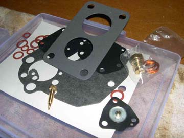
New "Royze" kit SO-10K as received — idling jet bottom left, carb mounting gasket top center
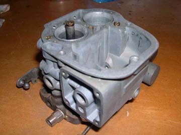
Carb disassembled and cleaned up
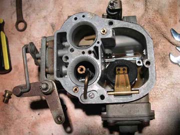
Part assembled with accelerator pump in place
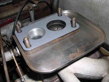
New mounting gasket and cleaned drip plate in place on manifold
New starter air valve parts ready for assembly

Top view: float in place, also top jets and injection tube #81
New fuel inlet needle valve #156 (brass) with mating surfaces of carb top #151 buffed up
General view; Reassembly nearly complete
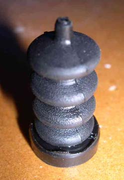
New dashpot bellows — refer to text
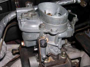
Front Solex Type 32 PAITA carburetor re-installed — note dashpot in front
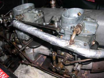
Both carbs renovated and in place — right side view
Both carbs renovated and in place — left side view
Priming Lever Operation
There is some information on this in the original Instruction Manual for the car. It is on page 32 of Edition A, (including Edition B). In particular there is description of the occasional situation where your priming lever appears to not operate properly:
"Every time the carburetor or fuel pipes have been emptied, or when the tank has become empty when driving, press down the hand lever on the fuel pump about 10 or 12 times. When doing this a slight resistance must be perceptible and the sound of fuel sucked in and sprayed into the carburetor must be clearly heard; the spraying noise will stop as soon as the carburetor is full. If no resistance is felt and if no sucking or spraying noise can be heard, which is possible at a certain position of the crankshaft, actuate the starter for a moment, so that the position of the crankshaft is altered and then the hand pump will function."
Addendum #1
I did the above work after the 220S broke down because of a fuel pump problem. I might say this is the first time my Mercedes-Benz Ponton has ever let me down.
In order to get me going and to speed things up I let a local mechanic "fix" it. The pump was full of a lot of accumulated debris and I knew that a reconditioning kit should be used. We made enquiries about a replacement pump by Pierburg and I was very pleased when it seemed to be available. However it turned out to be a "modern" version of the original mechanical one, fully sealed and the like. I said, "No."
The mechanic cleaned up the pump to get me going, but I was not happy with the result. It was not anywhere near clean, as you can see in my disassembly photos, and in particular I discovered that the spring on the priming lever was now broken. So I asked IPOG member, Phil Langlois if he had a reconditioned kit, and luckily he did. It also turned out to be the "long" version which was good news.
Anthony Tugwell
South Australia
1956 Mercedes-Benz Type W180 220S Ponton sedan
February 2007
Addendum #2 / Bellows Repair / April 12, 2007
|
Created: February 17, 2007 / Jeff Miller
© www.mbzponton.org