Illustration 1. Front brake parts
This page documents a front "brake job" on a 1957 Mercedes-Benz Type W121 190 Ponton sedan. Some of the text was compiled from archived email dating from 2002-2003. Otherwise, the narrative follows the tasks of removing and inspecting the front brakes, replacing the flexible hoses, checking the cylinders, replacing worn parts (friction washers, release springs, brake lines) re-lining the shoes, turning the drums — putting it all back together again, and bleeding the system. - Jeff Miller / May 31, 2004
Disassembly
Illustration 1. Front brake parts
The following items (reference Illustration 1) are for cars fitted with "automatically adjusting brake shoes"
- Item 3: Pin
- Item 4: Lock washer B14 DIN 127
- Item 9: Adjusting sleeve
- Item 10: Thrust washer (optional)
- Item 11: Friction washer (180 421 01 32)
- Item 12: Pressure spring
- Item 13: Tightening screw
- Item 14: Guide pin
- Item 15: Pressure spring (for guide pin at brake anchor)
- Item 16: Washer 5, 3 DIN 125 (for guide pin at brake anchor)
- Item 17: Cotter pin (for guide pin at brake anchor)
- Item 18: Release spring
There are four friction washers (Illustration 1, Item 11) used on each wheel, making a total of eight to do the front brakes. They are made out of a material similar to that of the brake linings. They get brittle with age and can cause adjustment problems. Only the "automatic adjusting" brakes (Illustration 1) have friction washers. If you have manual adjusters, you will have the big slotted, hex-headed bolts for adjusting on the brake plates. If the auto adjusters are slipping, it may be the washers, but may be the other hardware associated with it. The friction washers currently available from Mercedes-Benz are not as good as the originals. Whenever possible, reuse your originals. The new washers are gray, the originals dark brown. Both styles of washer are brittle, so handle them carefully. If you are forced to install new friction washers, put them on the outside of the shoes so you can check them for deformation. The new washers stretch and elongate, then break. Item 18 (Illustration 1) is the release spring (for front brake shoes) and is considered to be a maintenance item. There are two release springs per wheel.
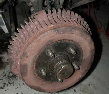
Photo 1. Right front brake drum mounted on wheel
Mercedes-Benz Pontons with four cylinder engines (W120/W121 series) have cast iron brake drums on all four wheels. The Ponton cabriolets (and other six cylinder models?) originally had aluminum drums up front and cast iron in the rear. The aluminum drums have a steel insert. The drums are interchangeable front to back, so some people recommend using the aluminum "alfins" (aluminum finned) for the rear to reduce weight.
A pulling problem could be sticking cylinders, blocked hoses, damaged shoes, or adjustment problems. One way to see if it is an adjustment problem is to see if the pulling is just due to a delay in braking or a difference in braking action when the braking is constant. This takes a road test, and it may take someone who knows or can feel the difference.
The drums do not always need to be turned or checked for run-out unless you have had noticeable problems with a pulsating brake pedal or shudder when applying the brakes. If there is a definite ridge inside the drum near the edge of the drum, such that it was hard to remove the drum from the shoes, then it is a good idea to have the drum turned. If the drum is uniform and does not have any major gouges, then use some 80 grit sand paper and scuff the drum to remove any glazing. The only problem with using sand paper is the conditions that created the glazing still exist, and it is only a temporary solution before they become glazed again. Any good brake shop can turn the drums, just be sure to impress upon them to take the minimum cut.
Terminology: In the context of this discussion, the terms, "arced " and "radiused " have the same meaning. Radius being half the diameter, thus the shoe is roughly half the diameter of the drum, hence, the shoe radius, or arc is matched to the drum radius or arc. However, there are nuances in the procedure.
Do the shoes have to be radiused to the drums? Some shops have the shoes radiused as part of the relining. The ideal situation is to have the drums right there when the shoes are arced. A micrometer for brake drums measures the I.D. (inside diameter) of the drum and then that information is repeated on the shoe arcing machine and you end up with a custom fit shoe. That way you end up with a set of shoes matched to a drum. If this is not done, you will probably never notice the difference in braking. It is rare to find anyone with this equipment anymore. So now that I have told you all about it, you might as well assume you cannot find it locally. If you can, take advantage of it. If not, your brakes will never know the difference.
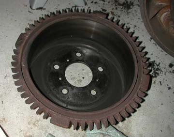
Photo 2. Brake drum removed
Remove the drum. If you are lucky, it will come off simply by pulling on it. If the brake drums are stuck in place, do not beat on the drum with a hammer. Notice the three small holes on the face of the drum. These are threaded for the common 8 x 1.25 mm bolt. Be sure the threads are clean, and uniformly screw in 3 bolts (40-45 mm long) and the drum will slowly come off.
Brake Drum Turning Dimensions
Type 190/220S
Standard
Maximum
9" cast iron
230 mm (9.062")
232 mm (9.141")
9" alfin (aluminum finned)
230 mm (9.062")
231 mm (9.101")
If there is enough metal left on them, you can have them turned by a machine shop or brake specialist. If not, a specialist can make extra thick linings for the shoes if you do not want to buy new drums.
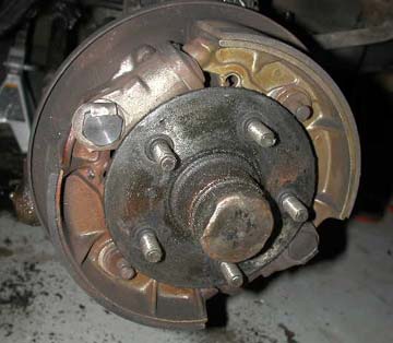
Photo 3. Right front brake assembly installed on car
The automatic adjusting, aluminum brake shoes and brake cylinders are visible in this photo. I installed new cylinders on this car in 1989 (15 years ago) so they may need honing after that length of time. Check the references at the bottom of this page to see where you can buy a cylinder hone. I was going to replace the hub grease cap because it is dented, but the Mercedes-Benz dealer wanted $56.00 for a new one. Fortunately, I found a used one in good condition for much less.
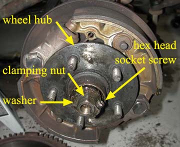
Photo 4. Annotated brake assembly and wheel hub
The wheel hub will need to be removed to gain access to the brakes and cylinders. Loosen the 6 mm hex socket (Allen) screw {threads are 7 mm x 1.0 mm x 24 mm (length)}. Note that original Ponton tool kits included a 6 mm hex (Allen) key for this particular application. The part number for this screw is 120-990-13-20. I bought a new one from MB as the one on the right wheel (in the photo) was pretty chewed up. I guess somebody did not have the 6 mm Allen key in their kit and they used something else (a chisel, perhaps?) to loosen it up. Unscrew the clamping nut and remove the washer and outer wheel bearing. Then pull the wheel hub off. While the hub is out, the wheel bearings and seals may be checked for condition, and greased.
To grease the wheel bearing, take the bearing and wash it out in mineral spirits, kerosene, gasoline, diesel fuel, and let dry. Then hold the bearing in your hand and force grease into it with the other, when there is grease covering and between all the rollers, it is ready for installation. Any good quality wheel bearing grease will do, but Mercedes-Benz sells their own (green) brand of bearing grease. It comes in a dispenser, which allows the exact measurement (65 grams) required for each wheel.
Illustration 2. Detail of front wheel
When replacing the hub (Illustration 2, Item 22) the clamping nut (Illustration 2, Item 31) should be tightened until the hub can not be moved by hand. Then back off on the nut just a little. You want to be able to turn the hub by hand with moderate force. This action is going to position the outer wheel bearing (Illustration 2, Item 27). There is a star shaped washer (Illustration 2, Item 30) behind the clamping nut that should be able to be moved with a screwdriver. For detail, see Job 33-4/4 in the Service Manual Model 190 (SM-1207-000).
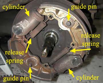
Photo 5. Annotated brake assembly with wheel hub removed
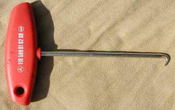
Photo 6. Multi-purpose spring puller — MB (116 589 01 62 00)
Remove the two release springs with (preferably) a spring puller. It makes the job much easier when you have the right tool. There are two styles of release springs for the Pontons. This 1957 Type 190 sedan has the later style springs, which attach to holes in the aluminum shoes.
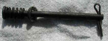
Photo 7. Guide pin, spring, washer, cotter pin
From behind the brake anchor plate, remove the cotter pins that hold the guide pins (under spring tension) in place. Here is the guide pin, spring, washer and cotter pin (Illustration 1, Items 14, 15, 16, 17). When removing the cotter pin from behind the brake anchor plate, be sure to keep your free hand on the head of the guide pin or risk loosing it when the spring tension is released and it becomes a mini projectile. The washer goes next to the cotter pin behind the brake anchor plate. The Service Manual Model 190 (SM-1207-000) has an illustration (Fig. 42-8/1) with the washer up against the spring on the front side of the brake anchor plate. Then, they have a footnote that states that later, the washer was fitted next to the cotter pin.
At least one of the brake cylinders need to be removed to get the shoes loose enough to come out. But first, the steel brake fluid hoses (Illustration 1, Items 40, 41, 45) will need to be unbolted (not necessarily removed) to gain access to the four brake cylinder bolts. Be careful not to mislay the copper washers (item 47 in Figure 1, above / metric 10 x 14 DIN 7603) that go with the steel brake hoses at the back of the anchor plate.

Photo 8. Brake anchor plate
The brake anchor plate with only one brake cylinder attached looks kind of naked. Note the four empty bolt holes where the other brake cylinder would be mounted. Also note the tubular holes for the guide pins at one o'clock and seven o'clock.
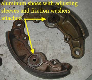
Photo 9. Aluminum shoes with adjusting sleeves
Ideally, a specialized tool is used (a modified 22 mm socket works well) to loosen the adjusting sleeves as they are circular with two opposing flat sides. They unscrew until the friction washers can be removed. Note that when replacing the adjusting sleeves they are screwed down all the way or until there is no more travel in the springs.
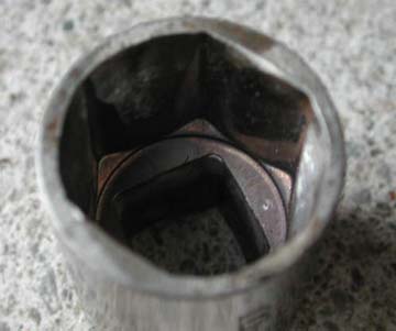
Photo 10. Modified 22 mm socket to remove adjusting sleeves
It is preferable to use a specially adapted tool to remove and re-install the adjusting sleeves (Illustration 1, Item 9). This photo shows a modified 22 mm socket used to perform the task. One has to grind out the "notches" of the 22 mm socket so that only the four half-corners engage the adjusting sleeve head. An adjustable wrench will also work, but the modified socket or special tool (M-B surely had one) really makes the job much easier.

Photo 11. Detail of adjusting sleeve on the shoe
Detail of the brake shoe with the adjusting sleeve and friction washers still attached. The friction washers are made of a material similar to the shoe lining. They are oriented so that they press against the aluminum body of the brake shoe. The metal washers go on the outside of the friction washers, away from the shoe. When removing or replacing the adjusting sleeves, the modified 22 mm socket fits on the head (Illustration 1, Item 13) of the sleeve (seen at the left side of this photo). The adjusting sleeve is screwed down all the way or until there is no more travel in the pressure springs (Illustration 1, Item 12, and seen in Photo 11). This at first may seem counter intuitive. Should the adjusting sleeves be so tight that the friction washers can not be moved along the shoe? Yes, that is correct because the normal force applied to the brakes is great and the shoes will move (adjust) under the pressure of braking. During re-assembly when the shoe is installed on the brake anchor plate again, the orientation of the adjusting sleeve is critical. It must be positioned such that the tubular holes for the guide pins (at one and seven o'clock) fall directly in the center of the adjusting sleeve. This is so that the adjusters are not starting out at one end or the other relating to their ability to "adjust." This is a key point, yet difficult to describe, so study the photo of the brake anchor plate (above) and the guide pin tubes to get a better understanding of it. Since the adjusting sleeves will already be torqued down when the shoe is re-installed on the anchor plate, there will be some minor adjustments needed (the shoe has to come off again) to get this orientation correct.
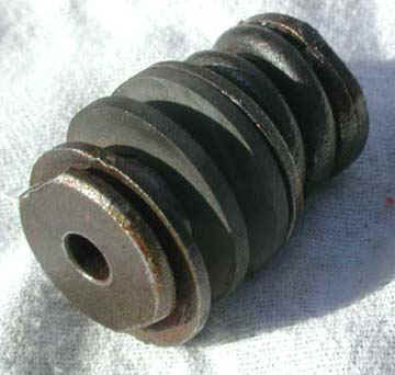
Photo 12. Detail of adjusting sleeve
Detail of the adjusting sleeve, friction washers and pressure spring (Illustration 1, Items 9, 10, 11, 12, 13) with the center guide pin removed. Observe the unique shape of the sleeve head.
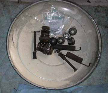
Photo 13. Upturned hubcap makes convenient parts storage area
Unless you have "show quality " hubcaps, they make a nice place to store the brake hardware until the shoes and drums come back from the restoration shop. I stored the parts for the left and right side brakes in two separate hubcaps just to keep things organized. WARNING: BRAKE FLUID DESTROYS PAINT! These parts were free of brake fluid, otherwise, I would not have stored them like this. The new cotter pins (in the plastic bags) were purchased at the local hardware store.
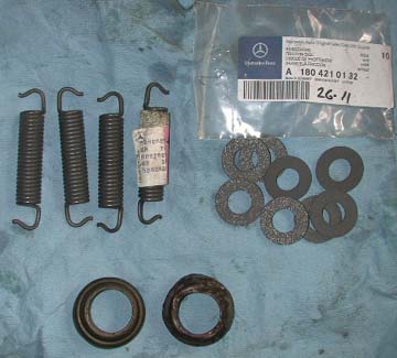
Photo 14. New release springs and friction washers
Some of the new parts I got for this job. Four release springs (Illustration 1, Item 18), eight friction washers (MB 180 421 01 32) (Illustration 1, Item 11) and a new metal end cap (Illustration 1, Item 32a) (to the left of the old one) for one of the brake cylinders.
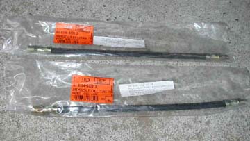
Photo 15. Flexible rubber brake hoses
Brakes on Mercedes-Benz Pontons require a certain amount of maintenance, especially after long periods of non-use (winter storage, etc.). When restoring Ponton brake systems, one will often find flexible hoses that have swelled internally from age and action of the fluid on the rubber. This reduces the internal diameter of the hose, restricting the back and forth flow of fluid that is necessary to provide maximum braking efficiency. Consider them a maintenance item every few years. Check for restricted flow by opening a bleed screw at each wheel cylinder. Fluid should come out easily.
A word of caution about removing the flex hoses. One does not want to snap the steel lines at the fitting on the engine side of the fender. That can easily happen by applying the rotational force to that nut, trying to break it loose from the hose's fitting. Rather, cut the old hose close to the fitting. Fit a flare wrench around the nut inside the fender and hold in place. Turn the fitting with a deep socket from inside the fender well. All this after soaking in penetrant (or ordinary white household vinegar).
Well, I tried to be careful, but I snapped both steel brake lines when removing the front brake hoses. Heat and penetrant did not help. I used a Dremel tool to cut the nut off the brake lines on the fender wall in the engine bay. In the process, I also did some damage to the retaining springs (Illustration 3, Item 39). They are still available from Mercedes-Benz.
Illustration 3. Flexible hoses, metal brake lines (not shown with complete accuracy), fittings, master brake cylinder
- 35: 120 420 10 29 / brake line / 2,375 mm (93.5 ") / master cylinder to right front fender
- 36: 120 420 02 28 / brake line / 381 mm (15 ") / master cylinder to left front fender
- 39: 000 428 03 73 / brake hose retaining spring (2 required)
The steel brake line from the right front side (Illustration 3, Item 35) is 2,375 mm long (including bends) to the master cylinder. It goes from the right front fender well and follows the frame rail around to the front of the radiator and back down the left frame rail and finally down to the master cylinder. The left side brake line (Illustration 3, Item 36) measures only 368 mm (including the bends) from the master cylinder to the fender well. To remove the brake lines at the master cylinder, you must remove the triangular metal plate under the car to gain access to the master cylinder. There are six or seven sheet metal screws holding the metal plate in place. Once I removed the plate, I had no problem removing the lines at the master cylinder. Most automotive parts stores sell brake lines in various lengths with the 10 x 1.0 mm threads and the European style "bubble " (convex) flare fittings at the end. The brake line diameter is very close to standard modern day sizes. Officially, the diameter is 4.75 mm. This is close to the 3/16 " diameter sold in parts stores everywhere. If you have them fabricated locally, it is fine if the metric end fittings are attached to the "standard " (English units) diameter line.
Brake Cylinders
There are two cylinders on each front brake of the Mercedes-Benz Pontons. The rear brakes have one cylinder per wheel. You can take them apart and see if they need honing. If they are rusted or scored, they will need honing. However, new brake cylinders are still available from Mercedes-Benz. After honing, use your finger and emery cloth to finish.
If you decide to repair the existing cylinders, you can simply buy the internal rubber cups from any auto store in the appropriate size: usually 1-1/8 inch front and 15/16 inch rear. Some earlier cars may be fitted with 1 inch cylinders in the rear, but these cups should also be available. Recall further that the wheel and master cylinders were not, repeat not, metric because Mercedes-Benz had a contract at the time with ATE in England or because ATE held some patent. Note, however, that the brake line fittings are all metric.
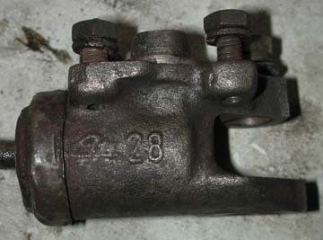
Photo 16. Detail of brake cylinder (note "ATE 28 ")
ATE front brake cylinder, 1-1/8 inch diameter (yes — English units!)The front cylinders should be 1-1/8 inch. If there is a marking on the outside, it will be: 28. That will stand for the mm equivalent of 28.57. If you see the number 26 marked on the outside, then indeed you do have 1-1/16 inch cylinders. The mm equivalent is 26.98. You should definitely see the number 26 or 28 raised on the outside of your master cylinder. Same indications. Note the cutoff chassis number indicated on p. 42-3/1 of the Service Manual Models 180 to 220SE (SM-1201-000).
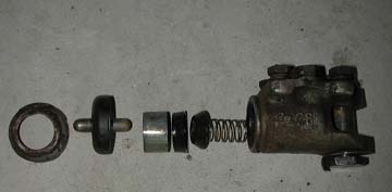
Photo 17. Brake wheel cylinder, disassembled, showing all of the internal and external parts
When I took the front cylinders off the brake anchor plate, only one seemed to have a small leak. I may have punctured the outer boot when removing it. So I repaired that one with an OEM (ATE) kit from SL Auto Haus. The cylinders were not otherwise scored or rusty but they did have some minimal brown sludge in them. Maybe the brown sludge was rust being held in suspension with the old brake fluid. I cleaned out the sludge with a rag and put them back together.
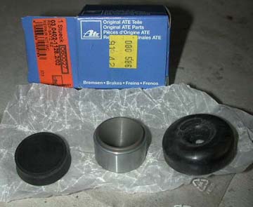
Photo 18. ATE cylinder rebuild kit
The ATE cylinder rebuild kit includes the internal rubber cup (left) (Illustration 1, Item 29), the steel piston (center) (Illustration 1, Item 30) and outer rubber boot (right) (Illustration 1, Item 31) and a set of instructions, nothing else. The concave section of the piston faces outward in the cylinder. The other side of the piston is flat.
After-Market Brake Cylinder Rebuild Kits (may be out-of-date)
NAPA lists front cylinder kits for the 1-1/8 inch wheel cylinders as number 264. Reportedly, it includes the internal cup, the internal spring, and the external dust cover. It lists as their number 13 the kit for the 5/16 inch rear cylinder. NAPA also lists as number 4313 from another manufacturer for the rear wheel kit, but there is a question whether this is still available from that manufacturer. NAPA also lists their number 424 for the front wheel cylinder with 1-1/16-inch bore. Prices differ at different NAPA outlets, so one needs to ask. Price quotes were about $7.00 for each kit.
Some NAPA outlets also list Beck/Arnley number 0713685 for the front, presumably including a new piston. This kit was more expensive. NAPA has no listing for the master cylinder.
NAPA still sells via its stores (and online) brake cylinder rebuilding kits for Pontons
- NAPA No. UBP264. Front. 1-1/8 inch bore. Internal cup, external boot, maybe internal spring. $8.99 list.
- NAPA No. UBP13. Rear. 15/16 inch bore. Internal cup, external boot, maybe internal spring. $7.49 list.
Possibly available through NAPA, but certainly available through other import car parts outlets:
- Beck/Arnley Worldparts No. BA-0713685. Front. 1-1/8 inch bore. Internal cup, external boot, no spring. $4.54 jobber.
- Beck/Arnley Worldparts No. BA-0712851. Front. 1-1/8 inch bore. Internal cup, external boot, piston, no spring. $16.78 jobber.
- Beck/Arnley Worldparts No. BA 0713602. Reportedly rear, although confusing because BA said bore is 26.22 mm, which does not equate to any of the required inch sizes. Some kits in stock but becoming obsolete. Internal cup, external boot, no spring. $6.49 jobber. One needs to check this further.
According to Beck/Arnley, the above items are manufactured by Overseas Automotive in Germany.
Re-assembly and Pressure Bleeding
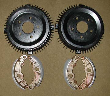
Photo 19. Drums and shoes — post restoration
Rochester Clutch & Brake shot blast the drums and painted them black. They are a matched set, i.e. the shoes on the left are matched with the drum on the left.
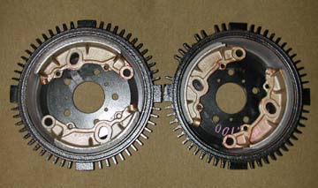
Photo 20. Matched set of drums with restored shoes inside
Rochester Clutch and Brake Company (RCB) was the shop that bonded (a.k.a. relined) the shoes and machined the drums. They were recommended by a Mercedes-Benz restoration shop in Massachusetts (Magno Restorations). Fortunately, RCB is about a 30 minute drive for me. The shoes on my Type 190 sedan were "cam ground " to the drums. Cam grinding is arcing the shoes so there is about .010 gap on either end of the shoe, this allows the shoe to contact the center first and wear or break in to the ends, ensuring full contact. If they arced the shoes perfectly, then the ends may contact first causing possible chatter and not seat properly. They did not recommend having the shoes arced perfectly for that reason.
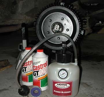
Photo 21. Brake fluid, roll of Teflon tape, and Power Bleeder
WARNING: BRAKE FLUID DESTROYS PAINT! Consider the "Power Bleeder" from Motive Products (www.motiveproducts.com) — it came highly recommended by other Ponton owners. I got the model that included the cap for European brake fluid reservoirs. The cap fit the brake fluid reservoir (original steel canister) on the 1957 Type 190 Ponton sedan perfectly.
- Fill the pump canister (two quart [1.89 liter] capacity) with new DOT 4 brake fluid. I used Castrol GT LMA brake fluid, which exceeds DOT 3 and DOT 4 specifications.
- Attach the Power Bleeder's cap to the vehicle's brake fluid reservoir. Be sure to get a good, tight seal. I used Teflon tape on the reservoir threads to insure an air tight seal because the original steel fluid reservoir on this 1957 190 has seen better days.
- Pump it up (includes an integrated plunger type hand pump) to about 15 psi.
- The kit also comes with a 12 inch (30 cm) length of clear rubber hose to attach to the bleeder screw at the wheel. The loose end of this hose goes into a jar (not included in the kit) to collect the excess fluid.
- Once the Power Bleeder canister is attached to the reservoir and pressurized, remove the rubber cap (Illustration 1, Item 34) and open the bleeder screw (Illustration 1, Item 33) at the right wheel. It only takes a second or two for the fluid in the right side brake line (all 93.5" of it) to start coming out the bleeder screw.
- Wait for all air bubbles to come out and tighten the bleeder screw again and replace the black rubber cap on the screw.
- Now, move to the other wheel, and do the same thing.
The nice thing about the Motive Products Power Bleeder is the size of the canister. It holds two quarts (32 fluid ounces) (1.89 liters) of fluid. This way you do not have to be concerned that you will start drawing air into the system when your smaller canister (as found with certain other kits) runs out of fluid. It is also easier to handle because of its larger size.
Discard any unused brake fluid. It will pick up ambient moisture and possibly dirt from sitting around in the garage. If you were able to pressurize the system for power bleeding, the chances that you have a leak are slim. But it still makes sense to take a look at the fittings to be sure there are no slow leaks.
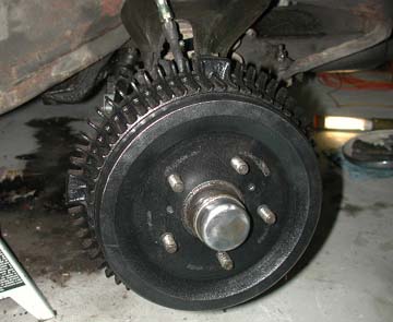
Photo 22. Restored drum on right front wheel
Compare this photo with the one at the top of this page. I was surprised the drum cleaned up so well. The original grease cap was replaced with a better one. When tightening the lug nuts on the wheel, the drum was not seating tightly. After a minute or two of looking at it, I decided to remove the drum and tighten up the wheel bearing. It was a little bit too loose. After that, all play was removed from the drum and the wheel.
Maintenance Advice and Tips
If, when braking, the car pulls to the left or right, check the brakes on the opposite side of the direction the car turned. If the car pulls right, check the left brake.
Very often, the pivot point of the brake shoes are corroded, creating friction so high that the shoes do not move in and out freely. Also, aged release springs can not overcome this friction effectively. Here is a suggestion: Remove the shoes and thoroughly clean any corrosion from the pivot pins and the I.D. of the shoe mounting bushing. Put a light coat of anti-seize paste on the pins and replace the shoes. Ascertain that the shoes are free to move on the pivot pins.
Release springs will eventually get "tired" and lose some of their tension. Replace them with fresh, strong ones.
Make sure there is no evidence of grease or brake fluid on the brake shoe linings or contact area of the drums. If so, check for wheel cylinder leaks or axle seal leaks.
If you need to replace the linings of the brake shoes, make sure that the drums are turned and the shoes properly "arced" to give full lining-to-drum contact when brakes are applied.
Make sure there are no dents, kinks, or leaks in the steel brake lines.
Following this advice, along with replacement of the rubber hoses should bring you back to "factory original" (or nearly so) brake performance. Admittedly, this is no substitute for disc brakes, but it should be a major improvement over what you have now, and may be good enough, depending on your driving style.
Mercedes-Benz Pontons with Power Assisted Brakes (Brake Boosters)
Do you have brake fluid disappearing slowly and you cannot see where? The master cylinder can leak slowly and the fluid dries up before you notice it. Or, the fluid is being drawn into the brake booster (if fitted). Rapid loss of fluid through the booster usually gets burned in the engine and makes it look like you are fogging mosquitoes. To stop the loss, unplug the vacuum line to the booster. Get the fluid out of the booster immediately. Brake fluid will ruin the rubber diaphragm inside the booster. Remove the vacuum check valve and drain the brake fluid out of the booster. Better yet, remove the booster from the car, undo the J-hooks holding the can on the booster, remove the can, and wash the diaphragm with alcohol or lacquer thinner. If you have a leather diaphragm, wash as above and soak in mineral oil. Are you bleeding the brakes after a brake job where you changed everything but the booster and the brake pedal never gets hard and you still get bubbles out of one of the wheel cylinders? Then, the booster is probably leaking. Pull the vacuum line under the booster (above the pedals) and check if the vacuum line is wet. When installing newly relined brake shoes, cover the lining with masking tape to keep grease off. When screwing all pieces of the brakes back together, if you cannot use your fingers to get the nut, bolt, or bake line screwed in most of the way, then stop. Something is wrong. This is especially true of the fine pitch brake fittings and the bolt screwed into the backing plate, through which the long thin pin passes and is held by a cotter pin.
Rolling Freely
On flat ground, parking brake off, car in neutral, you should be able to push the car easily. You should be able to back your legs against the bumper and nudge the car along. If you cannot, you have a dragging brake shoe, shoes, or wheel cylinders. Fix it. The same is true when in the car and stopped on a gentle hill. You should be able to release the brakes and the car will start to roll. If not, then the brakes are dragging. If you cannot figure out which shoe is bad or which wheel cylinder is stuck and cannot find a friend to push the brake pedal while you watch the brakes, then get out your video camera and video the brakes in action while you push on the brake pedal.
Uneven Brake Temperature
After a drive in the car, you can stop and put your hand on a wheel near the hubcap and feel the temperature of the brakes. If you get a dramatic temperature differential, check for dragging brakes or bad wheel bearings. This is a perfect place to use your no-contact infrared thermometer. If you do not have one, then get one. They are great for checking the cooling system, exhaust, making candy, checking your home's HVAC outlet temps, etc. After installing a new master cylinder, be sure to check for 1mm free play between the rod that is attached to the brake pedal and where it contacts the inside of the master cylinder. Given the choice of rebuilding a master cylinder or wheel cylinders vs. buying new, it is usually cheaper in the long run to buy new. This is especially true of the master cylinder. Shoe lining does not last forever. Assume a five year life. After that, replace them for maximum braking effect.
Silicone Brake Fluid
Silicone brake fluid is not recommended for Mercedes-Benz Pontons. It has been used with mixed results. It was installed in two identical 190SLs that had both received new wheel cylinders. The silicone fluid worked find in one car. In the other car, the fluid ran right out the wheel cylinders onto the ground. People say the reason for using silicone is that it will not absorb moisture. That is true. The moisture is not absorbed into the silicone fluid, the moisture stays in suspension in the fluid, but the moisture is still there, none the less. This defeats the reason for having silicone fluid. The brake fluid has to be flushed periodically to remove moisture, dirt, and rubber particles. So don’t waste your money on silicone brake fluid.
References
All illustrations on this page are from the Mercedes-Benz Type 190 Spare Parts List / Edition A / as per May, 1956.
Rochester Clutch and Brake Company (RCB) (www.rochesterclutch.com) relined and radiused the shoes and turned the drums. Sam Jr. was helpful and answered many of my questions via email. Incidentally, they do brake work for both Paul Russell's and Henry Magno's Mercedes-Benz restoration shops in Massachusetts.
SL Auto Haus / I used Ron Rapp's business in Virginia to get my hardware replacement parts such as release springs, friction washers, cylinder rebuild kit and metal end cap. See Links for website.
Some of the text on this page was compiled from archived email messages written during 2002-2003 between Doug Broome, Jim Davis, Henry Magno, Ron Rapp, Len Sokoloff, Rich Splaine, Ron van Seventer.
Brake cylinder hones are generally available at most automotive supply specialty stores such as Pep-Boys, Auto Zone, Sears, etc.
Photos and scans courtesy: Jeff Miller
Costs
The costs associated with working on the two front brakes only are listed here for reference, are quoted in USD, and were accurate as of May 31, 2004.
Friction washers: $7.50 each (SL Auto Haus) (8 required) = $60.00 total
Sheet metal cylinder cap for brake cylinder (SL Auto Haus): $4.25
Release springs (either early or late style, not both): late style (ends hook to hole) $5.50 each (4 required) (SL Auto Haus) = $22.00 total
For reference only: Release springs (either early or late style, not both): early style (ends hook to pin) $13.95 each (4 required) (SL Auto Haus) = $55.80 total
Front brake shoes (aluminum) re-lined (per RCB): $30 each (4 required) = $120.00 total
Front brake drum turning/machining (per RCB): $20.00 each (2 required) = $40.00 total
Front brake drum shot blasted and painted: $12.50 each (per RCB) (2 required) = $25.00 total
Cotter pins purchased at local hardware store. Nominal fee
For reference only: Brake drums (new, from MB): (180-421-08-01) (all four the same) $252.56 each (2 required) = $505.12 total
For reference only: Brake drums (used, cast iron): ~ $90 each (after-market sources) (2 required) = $180.00 total
For reference only: Brake cylinder (complete, new, from MB): $50.00 each (2 per each front wheel / 4 required) = $200.00 total
Brake cylinder repair kit (OEM / ATE part: 060027) (SL Auto Haus) $24.50
Brake cylinder repair kits (generic) (see discussion on kits elsewhere on this page)
For reference only: Brake cylinder hone: $15.00 (to refurbish old cylinders). See references for sources
Screw, 6 mm hex (Allen) socket (120-990-13-20) for wheel hub nut (Caliber Motors) $9.00
Front brake hoses: $25.00 each (Magno Restorations) (2 required) = $50.00 total
Steel brake line, right (Magno Restorations)
Steel brake line, left (Magno Restorations)
Brake hose retaining spring (2 required) (Magno Restorations)
Wheel hub grease cap (used, un-dented) (Phil Langlois) $5.00
Brake fluid: 64 Fluid ounces (1.89 liters), Castrol GT LMA (exceeds DOT 4) = Nominal fee
Motive Products Power Bleeder: $47.95 plus shipping ($8.27) = $56.22
Total cost of parts to do the front brakes: $415.97