Mercedes-Benz Ponton
Clutch Removal and Installation II
Andy Litkowiak / andylit@feralwombat.com / Illinois USA
1959 Mercedes-Benz Type 220S sedan
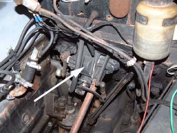
Photo1.
Andy Litkowiak / andylit@feralwombat.com / Illinois USA
1959 Mercedes-Benz Type 220S sedan
Photo1.
This is the top view of the shift lever linkage box prior to beginning. This photo also shows a linkage section that the manual indicates should be removed, but I can see no reason to. That would be the rod and ball linkage on the left side that attaches to the horseshoe shaped transfer bar. I left it connected and had no difficulties.
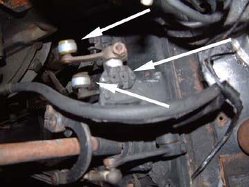
Photo 2.
This shot is a more direct view of the two linkage points to be disconnected. These rods extend back to the transmission itself. They are easy to pry off. Just get some leverage with small pry bar or large screwdriver and pop them off. In this photo you can also see the two electrical contact terminals for your reverse light harness.
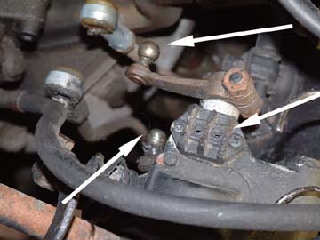
Photo 3.
Here are the two linkage bars disconnected. As stated earlier, these are very easy to pop off. The nylon ball housing is designed to be resilient and sturdy. This type of joint can handle quite a few removal/installation operations. This photo also offers a much clearer view of the reverse light terminals.
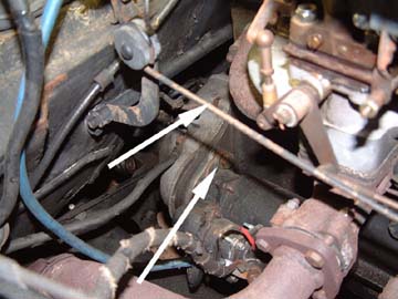
Photo 4.
The last activity on the top side involves removal of three bolts. The easiest is the top bolt for the starter. This also holds down the Negative battery cable and a grounding strap. Directly above the starter bolt on the bell housing side, you can see another bolt head. This is one of a pair of bolts that cannot be reached from the bottom. The twin is on the driver's side of the bell housing at the same height.
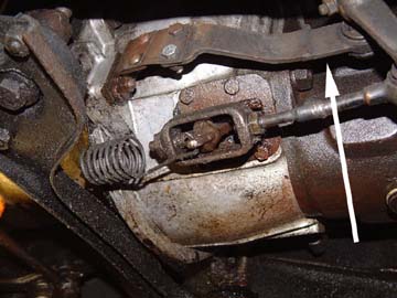
Photo 5.
This is the clutch linkage on the driver's side (US) of the bell housing. The flat bracket above the obvious linkage parts is a stabilizer intended keep the clutch linkage from banging around. This car has a completely mechanical clutch. No hydraulics at all.
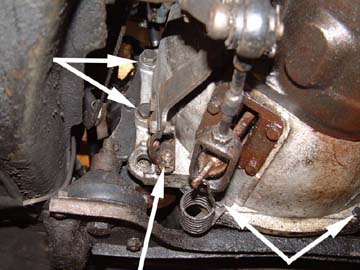
Photo 6.
This photo shows a different angle of the clutch linkage. You will first detach the linkage from the throw out arm. On the upper stabilizer bracket, you can see one of the two nuts that hold the bracket to bell housing. You will remove these nuts next. Do not bother to pull the bracket apart. It, and the linkage, can be tied off to the side.
Please note that there are four main bell housing bolts visible in this shot. On the left vertical surface you have two large bolts. On the bottom of the housing you see two smaller bolts, one at the far right of the photo and one just above, and to the right, of the spring. These must also be removed.
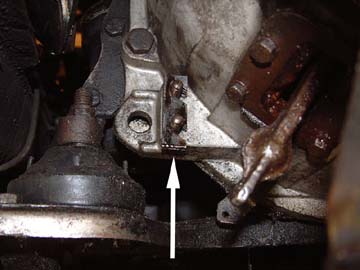
Photo 7. Once you remove the linkage stabilizer, you will find a
number of shims sitting on the studs.
Do not lose these little fellows.
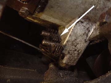
Photo 8. Close-up of the linkage stabilizer shims on the studs
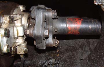
Photo 9.
Before you go any further, be sure to detach the drive shaft at the rear of the transmission. You need to pop out three bolts with cotter pins. I chose to do the rearmost, although I am not sure if it matters.
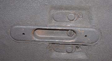
Photo 10.
After you have detached the shaft from the rear of the transmission, you will detach the center shaft carrier. Locate the cover plate midway to the rear of the shaft tunnel. The center bolt holds the cover and the two bolts on the sides hold the shaft carrier in place.
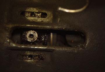
Photo 11.
Do not worry about marking the location. This will self-locate during re-installation (provided you do things in order).
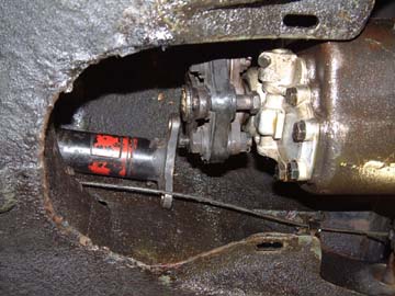
Photo 12.
Once you have detached the center carrier, you can push the drive shaft back out of the way. You do not need much clearance. Please note that you do NOT have to detach the shaft at the differential. The expansion fitting at the rear of the shaft has enough travel to allow the trans to drop.
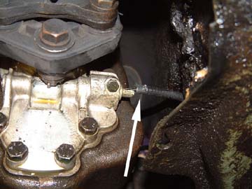
Photo 13.
The casualty in this photo is my speedometer cable. The cable must be removed from the transmission before you drop it. The nut visible next to the cable is loosened and the cable is withdrawn. In my case, the cable sheath has come loose from the end housing. This is almost certainly the cause of the speedometer jumping and hopping I get on occasion. To correct this for the short run, I opened up the end housing with a small flat screwdriver and re-inserted the sheath. I then secured it in place with a very small hose clamp. The end housing is a thin aluminum crush fitting. This should hold me until I get a new cable.
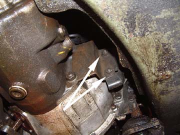
Photo 14.
This is a shot of the right side of the bell housing. Before you pull the last two bolts, you must remove the exhaust hanger support. First, you pop off the two small nuts visible in the photo. Then you remove the third bolt to the right of the bolts visible in this shot. Once you pull the third bolt, the support will come out, leaving you the steel "tab" attached to the transmission.
A word to the wise: If you think it is too tough to get that third bolt, think again. It is even tougher getting the transmission past that support bracket. I know, I tried it.
Another word to the wise: The idea may cross your mind that it would be easier to remove the transmission, then remove the bell housing. Wrong again. The transmission is attached with nuts and bolts. Those are not studs.
![]()
Photo 15.
Then, a miracle occurred and the transmission appeared on the floor. Sorry, no photos of that phase. It was too tough to shoot while we pulled it. You will need a floor jack (if you are on the ground) or a transmission jack. I strongly suggest two men for this job. The transmission is not too heavy, but it is a little awkward.
Removal consists of tapping the transmission backwards while the other guy holds it to be sure it does not drop. Mine came out fairly easily because of all the oil that had been spewing out of the engine over the years. I did not have a single stuck bolt.
You might experience some resistance if you have a dry motor and components. The most common hang up is that the transmission shaft hangs up on the clutch splines, the pilot bearing, or both. Persevere. A big rubber mallet is usually adequate to pull a stubborn transmission shaft.
You will do a bit of wiggling and shifting to get the entire unit clear. It is a little tight up there, but you can get it out.
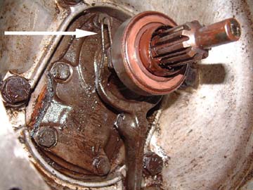
Photo 16.
This is the throw out bearing and the clutch fork. Do not inspect the bearing. ALWAYS replace the bearing when doing the clutch.
Before you pull the bearing, make careful note of the fork spring locations. Pull the springs before you pull the bearing. Do not lose them, your auto parts store probably does not carry this particular spring.
You will most likely need a puller for the bearing. Most auto parts store will rent or lend you one if you do not have one. I suggest buying a puller. They are very handy and usually required about 5 minutes after the parts store closes.
I will also suggest that you purchase the entire bearing assembly from Mercedes-Benz. You can just buy the bearing, but the bearing collars do wear over time. Why put a worn collar into a new bearing?
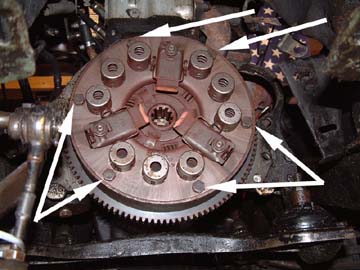
Photo 17.
There it is, the mother lode. This is what it is all about. The clutch. You will note the six bolts holding this in. You should pull these out criss-cross. Do not just work your way around the clock.
As you loosen these bolts, be very careful. The clutch is under pressure. At some point in the operation, before the last bolt is out, the outer plate is going to pop out a half inch or so. If your finger tip or knuckle is close enough, you could actually break a bone. At best, it will sting like hell.

Photo 18.
Once you have removed the clutch pressure plate and disc, this is what you will find. In this shot, the flywheel has already been cut. You will remove the 6 stretch screws to pull the flywheel. I suggest using an impact tool to remove them. Be careful when you pull the last screw. The flywheel is pretty heavy. If it falls, you could chip a tooth (yours or the car's).
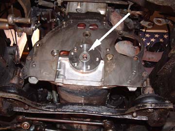
Photo 19.
Once the flywheel is out, you will encounter the pilot bearing cover. I forgot to shoot photos coming out, so we are stuck with the install photo. The cover is pried or pulled out. Behind this cover is the pilot bearing (sorry, no photo). I strongly recommend that you replace this bearing as well. Yours may be okay. Great. Clean it, oil it and put it on the shelf. I am a big believer in renewing wear parts when you are in a spot you will not be looking at again for a long time. You may as well have all the parts be the same age. To pull the cover and the bearing, I jury-rigged a puller. I took one arm from a small gear puller and clamped a pair of vice-grips to the opposite end of the arm. Insert puller arm, tap the pliers with a hammer. I do not have a slide puller (top of the to-buy list now).
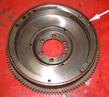
Photo 20.
Here is your flywheel after you have had it cut. In this photo, you can see that the parts shop machinist turned both the friction surface and the mounting surface (see arrow). At first, I wondered if this was correct. The difference between the mounting surface and friction surface must be maintained to spec. If you are taking a significant cut off the friction face you probably need to cut the mounting face too. So the machinist was correct to also cut the mounting surface.
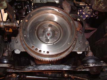
Photo 21.
Here is the flywheel back in again. Torque the screws to about 30-35 pound-feet. Use a torque wrench. Do not do this by touch. Be sure to clean the flywheel after installation. I suggest brake cleaner. It must be totally free of any grease, oil or dirt. In order to lock the flywheel while torqueing the screws, I used a very short medium sized flat screwdriver. I just lodged the tip between two teeth and set the base against the lower left motor mount. It worked perfectly.
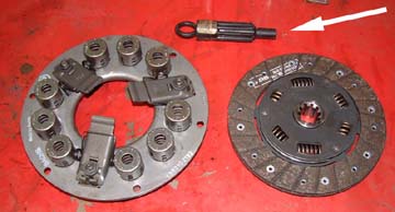
Photo 22.
Here is your new clutch. Please note the clutch tool. I would suggest you get one. It will make the installation go much smoother. I happened to have a tool from my Toyota Land Cruiser days. Luckily, it was a perfect fit.
The Toyota tool is available at: this link. If the link is dead, go to www.sor.com (Specter Off-Road, Inc.) and search for item # 200-11 (as of July 20, 2003). The tool is $8 and shipping will probably be about that much. I have not researched the Mercedes version of the tool.
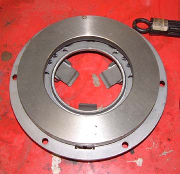
Photo 23.
As with the flywheel, be sure to clean the clutch plate pressure surface with brake cleaner. Do not clean the disc.
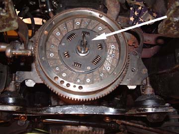
Photo 24.
Here is your clutch tool in action. This little beauty slides into the disc splines and then seats in the pilot bearing. It holds the disc in perfect alignment as you install the pressure plate.
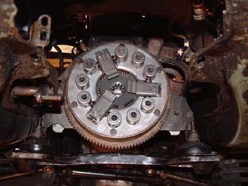
Photo 25.
Here is your new clutch, ready to accept the transmission and bell housing. To go forward from here, just follow the earlier steps in reverse. It is pretty straight forward. To adjust your clutch, simply run the mechanical linkage out to the end and start working your way in until it catches. Begin testing where the pedal engages until you have a nice smooth engagement.
Photo 26.
And finally, a word about safety to all. Always wear eye protection when working on your car. You never know what my break, move, slip or just plain fly off the car. All it takes is a little glob of gritty grease plopped into your eye and you are spending the rest of the day in the emergency room.
- Andy Litkowiak / July 19, 2003