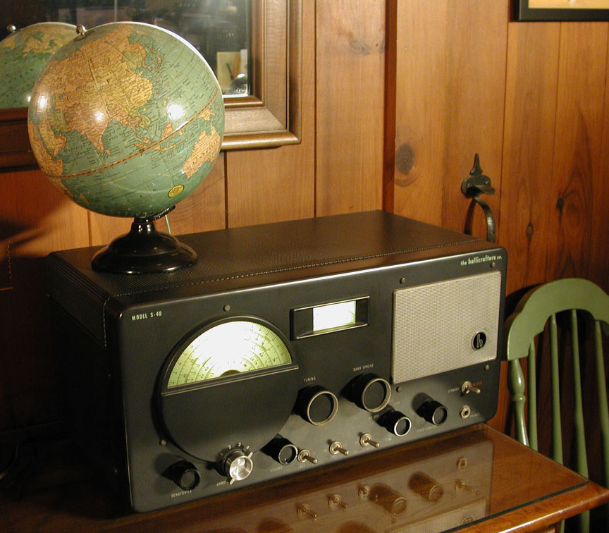
Photo 1. Hallicrafters "Model S-40"
This page chronicles repairs made to a Hallicrafters Model "Model S-40" AM/CW receiver. Latest revisions are at the bottom of the page.
Photo 1. Hallicrafters "Model S-40"
Hallicrafters (Chicago, Illinois, USA) "Model S-40"
Years Produced: 1946-1948
Photo: October 4, 2007
Incidentally, the 8" Terrestrial Globe on top of the Hallicrafters "Model S-40" was manufactured by the Geo. F. Cram Company of Indianapolis, Indiana. It is a Model "80", and includes the country of Italian East Africa which only existed from 1936-1941. It also includes short wave radio stations around the globe and their call signs. The symbol for the short wave stations is a red antenna tower.
Tuning Range
Band 1 (broadcast): 550 - 1700 kHz
Band 2 (short-wave): 1.68 - 5.4 MHz
Band 3 (short-wave): 5.3 - 15.8 MHz
Band 4 (short-wave): 15.3 - 44 MHz
References
- Overview of the Hallicrafters Model S-40
- Schematic Diagram (1st and 2nd Revisions*) (Rider)
- Resistance Chart (per tube pin) (Rider)
- Schematic Diagram (large) (Sam's)
- Schematic Diagram (small) (Sam's)
- Schematic Diagram (small, with annotations) (Sam's)
- Sam's Photofact Set
- Period Advertisement
- Operating Instructions
- Troubleshooting The Audio Output Stage: www.radioremembered.org/output.htm
- Hammond "125BSE" Output Transformers: www.hammondmfg.com/125.htm
|
Table 1 |
||||
| Tube | Ref. Nr. | Type | Reference | Price |
| 6SG7 | V1 | RF Amplifier | www.r-type.org/exhib/aaa0056.htm | $6.50 |
| 6SA7 | V2 | Mixer & Local Oscillator | $3.90 | |
| 6SK7 | V3, V4 | (2 req'd.) First & Second IF Amps | $5.95 | |
| 6SQ7 | V5 | AGC Detector & First Audio Amplifier | www.r-type.org/exhib/aaa0054.htm | $5.95 |
| 6F6G | V6 | Power Audio Output | $12.00 | |
| 6H6 | V7 | AVC & Noise Limiter | www.r-type.org/exhib/aaa0330.htm | $2.60 |
| 6J5GT | V8 | BFO (Beat Frequency Oscillator) | www.r-type.org/exb/exb02777.htm | $6.40 |
| 80 | V9 | Rectifier | www.r-type.org/exhib/aaa0296.htm | $27.40 |
Tuning Dial Pilot Lamps
Two lamps required. Type # 44 (bayonet base, 6.3 volt, 0.25 amp, bead color: blue). The pilot lamps are typically sold in packages of 10 at vintage radio swap meets and by the usual online sources. See Links. Ordered a box of 10 Type # 44 lamps from AES (Antique Electronic Supply) on October 2, 2007. Price was $2.95.
Purchase and OverviewI discovered this antique receiver on Saturday September 29, 2007 at the Elmira Hamfest. I was attracted by its mysterious and slightly sinister (if possible) appearance. It looked like it was from an old science-fiction movie. The real mystery of course, was how well it performed. The asking price was $145. The selling price was $125, no manuals included. Vendors were John (KW2JR) (was KF2JQ at the time of sale) and his wife, a familiar team at regional hamfests and radio swap meets. Overall, the cosmetic condition was very good, and they assured me it worked well and had decent audio. So, I took the leap of faith and bought my first Hallicrafters set.
Upon getting it home, I removed the knobs with a with a 1/16" hex (Allen) key and cleaned them in warm water with a toothbrush and Murphy's Oil Soap. I also gently rubbed a few spots off the cabinet with a damp cloth. With minimal effort, this radio was looking like new again. I had to reorganize the shack because the radio was larger than it looked at the Hamfest! The S-40 requires an external antenna, and I simply used a ten foot length of #22 AWG wire hung up around the shack with surprisingly good results. It also has two terminals for a balanced line (300 Ω twin lead) dipole.
After dinner, I listened to English broadcast services from Spain, Germany and Japan on the 49 meter band, near 6 MHz. The audio clarity and tone was quite good. Even though the Hallicrafters model S-40 is a single conversion receiver, only the slightest touch of the tuning knob was needed to receive adjacent signals. Maybe if the the bands were more crowded, or if the antenna was longer, it would have been a different situation. In October 2007, we are at the bottom of the sunspot cycle, so the single conversion may become more of a problem when the band conditions improve.
A unexpected feature was the ability to copy Single Side Band (SSB) amateur stations by placing the AM/CW toggle switch in the CW position, and adjusting the BFO pitch control along with the Bandspread dial. I was able to copy both upper and lower SSB conversations with a little bit of tuning effort. I was not sure this would be possible, and was pleasantly surprised. I had to adjust the Bandspread about every two minutes as the set warmed up, and drifted off frequency.
BreakdownOctober 8, 2007 (Monday): After I got home from work, I was surfing 80 meters, when the speaker suddenly fell silent. I tried the other three bands, but none of them had any audio whatsoever. The dial lights were still on, and then, a little plume of smoke began rising up out of the top. There was no popping or anything, it just died quietly. After only nine days of good short-wave listening, the Hallicrafters S-40 finally fell victim to advanced age. Good timing on the vendor's part! So, I quickly unplugged it from the mains and carried it down to the workshop to inspect the damage. I could not believe it still had the original Hallicrafters Factory Warranty seal on the bottom of the cabinet. Was it possible it had never been serviced in six decades? The warranty seal was affixed to the bottom of the metal cabinet with four rivets which were themselves sealed with green paint. One rivet was missing. The paper seal appeared to be affixed in such a way as to preclude opening the cabinet without breaking the seal, but I was not sure about that. I originally assumed the radio had been worked on at some point, because the power cord seemed flexible and probably not original, but the vendor said it was stored in his mother's attic for a "long time." So, who knows? If the components were all original, it is understandable why it failed. So, I moved the Zenith "Trans-Oceanic B600" off the workbench and began working on the Hallicrafters "Model S-40" instead.
Repair HistoryOctober 9, 2007 (Tuesday): The .pdf files I found on the internet were low quality. Needed to get a copy of the original. So I went to public library and photocopied the complete Sam's Photofact Set (462-19). Cost to make copies was $.20 per page. The Sam's Photofact Set for the Hallicrafters S-40 was seven pages, so it cost $1.40. Now, I was able to read the schematic. But, was it the correct schematic for my radio? Read further to find out.
October 22, 2007 (Monday): Removed the original Hallicrafters Factory Warranty seal from the bottom of the cabinet and extracted the radio chassis. The three warranty card rivets (originally, there were four) were removed with a thin putty knife. The chassis and faceplate slides out the front of the cabinet, which is a real nice design feature. After studying the schematic, I grabbed some replacement parts (capacitors and power resistors) at Radio Daze.
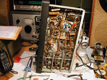
Photo 2. Under the Hallicrafters S-40 (before capacitor replacement began)
Determined that the "smoking" component was R54, a 1.5k Ω, 10 watt power "plate dropping" resistor. Turned the power on, and it began to smoke after about 20 seconds. Suspect that one (or more) of the capacitors along the high voltage (B+) line is shorted to ground, causing all the high voltage (B+) current to overheat the resistor. I plan to change the resistor and all suspect capacitors. The schematic and parts list indicate that R54 should be a 1k Ω, 10 watt resistor. Will replace it with the correct value.October 23, 2007 (Tuesday):
- Disabled and superseded the Sprague combination 3-section capacitor canister by replacing it with discreet electrolytic capacitors. Schematic part numbers and values for the new individual capacitors were: 10A (33µF 450v), 10B (10µF 450v), 10C (10µF 450v). Left the original Sprague canister in the chassis to preserve the appearance. The canister was annotated, "20 - 40 µF", "8 - 20 µF", "8 - 20 µF", "TVLU 379..." Could not see the remaining text without removing the canister.
- Replaced C17 (0.002µF 1000v) (with 0.0022µF 600v).
- Replace R54 (1.0k Ω, 10 watt). Determined that the smoking component was R54, "plate dropping resistor." Amazingly, it still measured 1.5k Ω (not the original value per schematic however, so was it replaced before?). Wait until the short in the B circuit is fixed before replacing this resistor or it may overheat and burn up again.
- Replaced C13 (0.05µF 400v) with a 0.047µF 600v.
- Replaced C14 (0.1µF 400v) with 0.1µF 600v.
- Replaced C25 (0.05µF 400v) with 0.047µF 600v.
- Replaced R53 (12k Ω, 5 watt) with a 10k 5w and a 2k 5w wired in series. The original R53 (radial/tubular style resistor) measured 18k Ω.
Table 2
Replacement Parts for Hallicrafters S-40
Compiled: 22-oct-2007 through 25-oct-2007. Placed order: multiple days
Vendor 1: RD (Radio Daze) - www.radiosupply.com
Vendor 2 (for reference): AES (Antique Electronic Supply) - www.tubesandmore.comSchematic part number Original component and composition Value (original) Value (replacement) Composition of new part Vendor (Part number) Price ($) Quantity (actual) Purchased / Ordered Date Total ($) R51 ? 1k ½w carbon composition RD (R-CCA-1K-5) 0.95 pack of 5 24-oct-2007 R53 radial/tubular 12k 5w 10k 5w + 2k 5w in series metal oxide power resistor RD (R-PW5-10K) RD (R-PW5-2.0K) 0.50, 0.37 1 1 each 22-oct-2007 R54 cement type 1.5k 10w (incorrect value) 1k 10w (correct per schematic) metal oxide, cement style power resistor RD (R-PW10-1.0K) 0.50 1 1 22-oct-2007 R65 radial/tubular 10k 2w 10k 2w metal oxide RD (R-MOB10K-5) 0.85 pack of 5 24-oct-2007 R73 ? 470 5w 470 5w metal oxide RD (R-PW5-470) 0.37 1 1 22-oct-2007 10A electrolytic 30µF 450v 33µF 450v axial electrolytic RD (C-EA33-450) 1.99 1 1 22-oct-2007 10B electrolytic 10µF 450v 10µF 450v axial electrolytic RD (C-EA10-450) 0.99 1 1 22-oct-2007 10C electrolytic 10µF 450v 10µF 450v axial electrolytic RD (C-EA10-450) 0.99 1 1 22-oct-2007 C11 paper, electrolytic 30µF 25v 33µF 50v axial electrolytic RD (C-EA33-50) 0.69 1 2 25-oct-2007 C13 paper 0.05µF 400v 0.047µF 600v 715P "orange drop" had in stock N/A N/A N/A N/A N/A C14 paper 0.1µF 400v 0.1 µF 600v 715P "orange drop" had in stock N/A N/A N/A N/A N/A C17 paper 0.002µF 1000v 0.0022µF 600v 715P "orange drop" had in stock N/A N/A N/A N/A N/A C25 paper 0.05µF 400v 0.047µF 600v 715P "orange drop" had in stock N/A N/A N/A N/A N/A C32 ? 270 pF 500v 270 pF 500v silver mica RD (C-SMR-270-500) 0.62 1 2 25-oct-2007 various paper 0.1µF 400v 0.1µF 600v 715P "orange drop" RD (C-OD15.1-600) 1.20 5 24-oct-2007 various paper 0.01µF 400v 0.01µF 600v 715P "orange drop" RD (C-OD15.01-600) 0.64 5 24-oct-2007 various paper 0.02µF 600v 0.022µF 600v 715P "orange drop" RD (C-OD15.022-600) 0.70 10 24-oct-2007 various paper 0.002µF 1000v 0.0022µF 600v 715P "orange drop" RD (C-OD15.0022-600) 0.54 5 24-oct-2007 various paper 0.05µF 200v 0.047µF 600v 715P "orange drop" RD (C-OD15.047-600) 0.72 12 24-oct-2007 various paper N/A (mistake) 0.47µF 630v axial lead metallized polyester film RD (C-MF.47-630) 0.93 5 24-oct-2007
Repair History, Continued
October 24, 2007 (Wednesday):
- Placed order with Radio Daze (See Table 2). Picked up on way home.
- Replace C18 0.02µF with 0.022µF.
- C11 (30 µF 25v) measured in the nano-Farad range. Will investigate.
Found a problem with capacitor C11 (30µF 25v, electrolytic) on the cathode of the 6F6G output tube. It measured very low capacitance (nano-Farad range) with my Craftsman DMM. If the capacitor were shorted, it might cause the 6F6G tube to draw too much current and cause R54 to overheat. But, I was able to get capacitor C11 to "charge up" on my old Bakelite Triplett VOM (with the meter in Ω mode). After about 10-15 seconds, if the capacitor is good, the resistance reading on the VOM should rise slowly. So that test indicated C11 was still good. With one lead of C11 disconnected from the circuit, it did not make any difference when I switched the power on. Resistor R54 still smoked. So I will pick up a new (modern equivalent: 33µF 50v) electrolytic capacitor tomorrow and see if it makes any difference.
Hallicrafters S-40 "2nd Revision"
Fellow ham, and AWA member, Lynn (W2BSN) located the Rider schematics for the Hallicrafters S-40 at the AWA Annex yesterday, and sent me copies. I then compared the Rider schematics with my radio. There were apparently three different revisions of the Hallicrafters S-40. This might explain why the Sam's Photofact Set shows components where there are no components! Case in point: R73 (470 Ω 5w) is not in my radio, but is shown on the Sam's schematic directly to the right of the smoking resistor (R54). Also, SO3 and PL3 are shown in the Sam's schematic and the 1st Revision of the Rider schematic, but not the 2nd Revision. My radio does not have a plug (PL) and socket (SO) for the output transformer.Based upon the Rider schematics, I hereby conclude that I have the "2nd revision" of the Hallicrafters S-40. The Rider schematic for the "2nd revision" is the only one (compared with the Sam's Photofact Set, and the "1st revision" of the Rider schematic) that does not have "SO3" and "PL3" (socket 3 and plug 3) for the connection at the output transformer. My S-40 radio does not have a plug and socket. The primary of the output transformer is hard wired into the circuit.
October 25, 2007 (Thursday):
- Picked up replacements for C11 (modern equivalent: 33µF 50v) and C32 (270pF 500v) from Radio Daze on my way into work.
- Replaced C11, but there was no change.
- Replaced a 0.02µF paper capacitor, but not sure which one it was. It was wired between V8 pin 6 (6J5GT - BFO) and the V5 pin 6 (AGC Detector & First Audio Amplifier) (plate - B+)
October 26, 2007 (Friday):
Without a tube tester, or a decent printed tube manual, my ability to verify the tubes and read the pin numbers on the schematic was limited. There are tube pin-outs in the reference section of Table 1 but it was a challenge not to have a printed reference in front of me when needed.
Next, I planned to disconnect the output transformer (75) leads from the 6F6-G tube. The schematic shows a "plug and socket" (PL3 and SO3), but it is actually hard wired. The output transformer (75) looks like it might be capable of causing the low resistance problem at the plate (pin 6) of the 6F6-G output tube. So, disconnecting the transformer may change the resistance reading on that pin. If the resistance is back up to where the Rider document suggests (25k Ω) then the output transformer becomes more suspect. Universal output transformers should be readily available, if needed.
October 27, 2007 (Saturday):
Lynn (W2BSN) provided a Type A-3856 output transformer to try as a substitute for the Type A-3877. The Type A-3856 is designed for push-pull output tubes, but can also be used in single output tube circuits. Just ignore the center wire on the primary side. He also provided two RCA Receiving Tube Manuals (c. 1940, 1961) and a 1944 ARRL Handbook, which has numerous tube pin-outs in the back. The Hallicrafters parts list identifies "75" (output transformer) as a Stancor model A-3877. However, the Stancor data sheet specifies a A-3878 or A-3822 (universal type) for the 6F6-G tube! Nobody ever said it would be uncomplicated! Since I now have the Type A-3856 transformer, which is very close in specs as both the A-3877 and the and the A-3878 or A-3822 (different mounting styles), I need to figure out which secondary taps to use on the "voice coil" (small coil shown on 76 in schematic) given the specifications on the Hallicrafters parts list and the Stancor data sheet.
The "voice coil" impedance of the speaker is listed on the Hallicrafters S-40 parts list as 3.3 Ω. So, according to this page: www.hammondmfg.com/125.htm the hookup pins for the secondary of a Hammond 125 series push-pull output transformer (similar to the A-3856 test unit) should be: pins 4 and 6. This gives a total primary impedance of about 5,000 Ω which is about what the output transformer has. I believe the goal (for any given voice coil impedance) is to use the two output taps which provide the closest value to the primary impedance (as specified in the parts list) for the original output transformer. In this case, the voice coil impedance is listed as 3.3 Ω, and the output transformer primary impedance is 5,010 Ω.
Radio Daze indicated they no longer made tabbed transformers, and recommend a Hammond HX 125BSE, which sold for $33.54. You will need to drill holes for this, but it is a quick refit job.
References for Output TransformersOctober 28, 2007 (Sunday):
Tested all tubes (except the Type 80 rectifier) at the AWA Museum, and they were good. The tube tester at the Museum did not have a 4-pin socket for the Type 80 tube. I was told that as long as the tube lights up in the radio, it is probably okay. I did not see it lighting up, but it was getting extremely hot.
October 29, 2007 (Monday):
Verified that the original output transformer was working. Unsoldered the transformer wires in the circuit and used jumper wires to put the Type A-3856 output transformer into the circuit. There was no change. Still no audio, and R54 is still getting very hot and turning brown.
Re-measured the DC voltage at the output pins of the Type 80 rectifier tube. It was 250 Vdc. The bottom left of the Rider Schematic indicates it should have 340 Vdc on the output. Not sure if this is significant.
Re-measured the B+ at pin 6 of the 6F6-G tube and it was 50V. The bottom left corner of the Rider Schematic indicates it should have 240V. This is definitely too low. Still need to identify the root cause of this problem.
October 29, 2007 (Monday):
Decided to replace each and every wax paper capacitor. Also noted that a new Type 80 rectifier tube costs $12.50 (Radio Daze). Might try to get Radio Daze to test my Type 80 tube. The tube testers I have had access to thus far have not have the capability of testing a 4-pin Type 80 tube.
October 30, 2007 (Tuesday):
I got the radio working again this evening by changing four more wax paper capacitors and a resistor which measured far above its original value. Replaced C12 (0.01 µF, 400v, "DC block BFO trans."), C15 (0.01 µF, 400v, "line filter"), and two "ambiguously documented" capacitors.
One of the undocumented capacitors was a 0.02 µF tied to R49 (10 Ω, ½ w) near the V4 (6SK7) socket. It may have been one of the three unmarked band switch (95) capacitors (see Sam's schematic). The Rider schematic sequentially numbers the band switch capacitors, but provides no values, and I did not have the Rider parts list to use as a cross reference. Also, there were no other capacitors nearby in the chassis which might be the other band switch caps. So, as yet, I am unsure what capacitor this was.
The other "mysterious" capacitor (probably C22 - shown as 0.05 µF on the Sam's schematic) was tied to V4 (6SK7), pin 3 (grid 3) and pin 5 (cathode) with a value of 0.04 µF. There were no 0.04 µF capacitors listed on the Sam's Photofact parts list, but C22 was called "6SK7 cath. bypass", so this was probably it. Note that this 0.04 µF wax paper capacitor was different from the others. The OEM (Original Equipment ManµFacturer) was Sprague. This one was made by "Industrial Condenser Corporation" (Chicago, Illinois). It had dried wax oozing out one end, which was not a real good sign. Also, R49 (nearby) looked pretty crispy. Had I paid more attention to this during my initial visual inspection, it might have led to a quicker resolution. I still planned to replace all of the remaining paper capacitors before I put the radio back into service.
With one lead removed from the circuit, resistor R49 (10 Ω, ½ w, "osc. suppressor") measured about 650 Ω. Replaced it with a new one, and replaced both the "ambiguously documented" wax paper capacitors with modern equivalent values (0.022 µF and 0.047 µF).
As soon as the radio began working, I tuned across the bands to check the alignment against the dial reading. About a minute later, the main tuning dial cord broke! So, I followed the dial cord diagram on the Rider schematic and was able to re-string a new cord in about 15 minutes.
The vendor at the Elmira Hamfest sold this radio at the exact right time. When I bought it, a little over four weeks ago (September 29, 2007) everything was original, the cabinet looked real sharp, and the radio was working fine. But as I have read many times, an old vacuum tube radio should have its wax paper capacitors replaced. It is not a question of "if" they will fail, it is a question of "when" they will fail. The dial cord was another thing that failed simply due to old age. So, while an original, unrestored tube radio may be a nice relic to own, it may not be suited for daily use until some upgrades have been made. Any book that deals with old radio restoration will state this quite clearly. I learned it first hand with this radio.
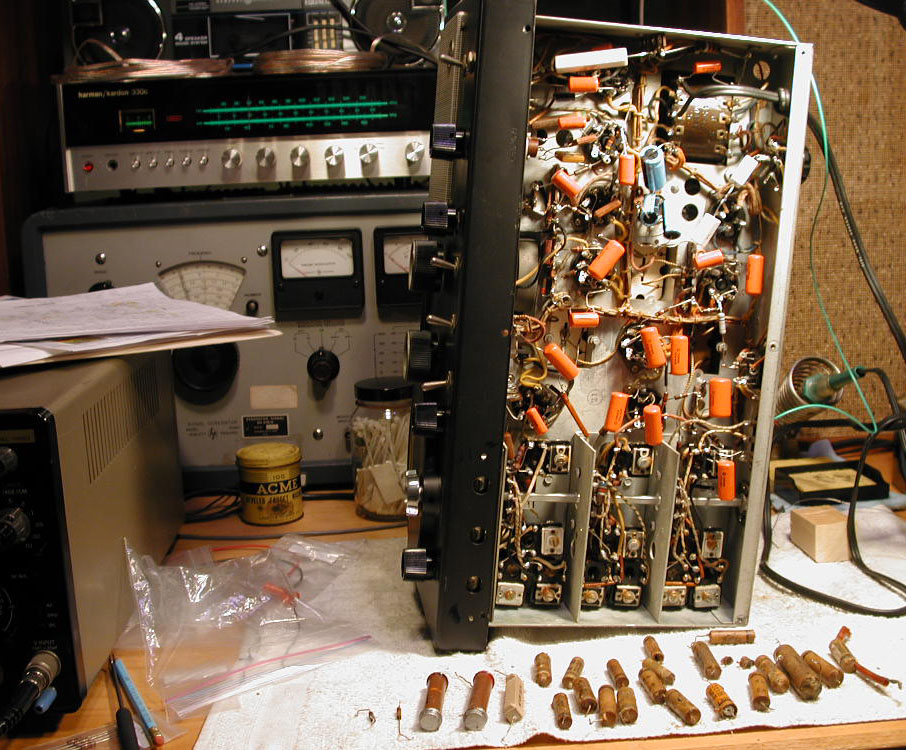
Photo 3. Capacitors Replaced
November 3, 2007: All wax paper capacitors and bad resistors replaced – moments before the chassis was put back into the cabinet. Will it be good for another 61 years? Check this page again in 2068 to find out.
Acknowledgements
- Lynn (W2BSN) (Rider schematics, Model A-3856 output transformer, Stancor transformer data sheet, 1940 RCA Receiver Tube Manual, 1961 RCA Receiver Tube Manual, 1944 ARRL Handbook, and much needed encouragement).
- Bill (WA2LVP) (Hickok model 6000A portable suitcase style tube tester). Note the 6000A did not have data for the 6F6-G tube, or the Type 80 rectifier tube. No other tube listings for the Hallicrafters S-40 were checked against the Hickok 6000A. Instead, I used the AWA Museum tube tester, but want to acknowledge Bill for loaning me his. If nothing else, it illustrated how portable tube testers are not always capable of testing each and every tube. The Hickok 6000A was also borrowed for the Grundig 2066PX radio work, but had none of those tubes listed either. Something to keep in mind when shopping for a tube tester.

c o n t a c t / r a d i o w o r l d
1946-1949 Hallicrafters "Model S-40" General Coverage Short-Wave Receiver
Established: October 9, 2007
© Black Sparrow Photography / Jeffrey P. Miller (N2AWA)
