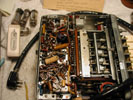
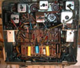
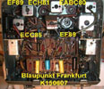
It continued to work well from 1989 up until the fall of 2010 when the audio volume dropped off significantly. At that time,
it was removed from the car, and the tube sockets were cleaned with DeoxIT. The tubes
tested fine, and the minor servicing seemed to fix the problem. Unfortunately, the next summer, during its seasonal maiden voyage (June 25, 2011) there was absolutely no audio of any kind coming from the speaker. I removed the radio, and the resulting experiences were chronicled on this page.
July 5, 2011
Borrowed an ex-Navy model "TV-7D/U" tube tester and verified all tubes were healthy.
Got an extra set of tubes in the bargain. Put the radio back together and installed it in
the car, but still had absolutely no audio (or sounds of any kind) from the speaker. Tested
the speaker, and it measured 8 ohms and crackled while being tested, so it seemed to be working.
Removed the power supply from under the dash. It was held in place with two large flat-blade screws.
Surprisingly, there were no wires (for 12 volt input?) or any other connections, aside from the
interconnection cable to the radio). The power supply was in perfect, unmolested physical condition.
The radio itself has three connections:
-
Aerial socket (on left side of chassis)
-
12 volts input supplied by a #12 AWG black wire from under the dash to an in-line screw terminal
that connects to an external yellow wire on the radio
-
Power supply interconnect cable (shielded, with a 6-pin Hirschmann® Bakelite plug)
The power supply has two connections:
-
Interconnect cable socket (accepts the 6-pin Bakelite plug)
-
Speaker (8 Ω with a two-conductor wire and two-pin plug). The speaker plugs into the power supply unit.
The power supply (includes the EL84 amplifier tube) must first get its power from the radio
(via the interconnect cable) and then supplies the radio with the B+ high voltage. The power
supply includes an output tube type EL84 and a chopper (a.k.a. vibrator). There should be 225
volts coming out at pin 1 of the multi pin connector.
According to the Operating Manual for the B&K (B+K) Precision Model 1460 oscilloscope it features a calibration jack (bottom left of front panel) that generates a 1 kHz signal (5 V p-p square wave). When the probe from the calibration jack is touched to certain parts of the circuit, an audible signal should be heard. Touched the probe to pin 2 of the EL84 tube and there was indeed audio at the speaker. On the other side of the 1 k Ω resistor (directly off pin 2 of the EL84) there was no audio. This test provided some idea of where to start looking for the problem. It could have been the 500 k Ω resistor (annotated “0.5 M” in the schematic - see References), or the 0.5 µF capacitor, or possibly with the interconnect cable. It appeared as though something was shorted to ground.
July 7, 2011
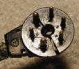
The 6-pin Bakelite plug was broken, and the ground wire (pin 3) was disconnected from the outer
braided shield jacket. The insulation on the wires was in poor condition, and there was a dead short between
pin 6 (off pin 2 of the EL84) and 3 (ground/shield) so I addressed that.
The insulation was so bad, I was not sure if I could use the existing wires. I re-soldered the pin 3
wire to the braided shield, but still no audio (unbelievable!) out the speaker.
The short between pin 3 and 6 of the connector (on the radio side of the cable) told me I needed to look at that. The power supply was off the radar for the short term.
13-jul-2011: Per Karl Horst (British Columbia, Canada) these connectors were very common on other equipment.
Ericsson used them on their intercom systems in the 1960s to 1980s. There is a huge German
mail-order house for electronic parts called Conrad. Try searching the
internet on both companies and send them these photos, and they may be able to
direct me to a source of new connector.
July 11, 2011
Building a new interconnect cable. I bought some audio cable from
Radio Shack for the shielded audio line. Its diameter is a little on the large side, so
I may be forced to use a regular wire with the braided shield from RG-174 coax (about the
diameter of a ball point pen refill). The goal is to get all the wires of the interconnect cable
through the bottom opening of the original Hirschmann connector. I will try to do that with the
heaviest gauge wire possible - that might mean #16 AWG. I am wire poor at the moment. I have
smaller wire and larger wire, but no #16 AWG.
For the outer braided shield jacket (encases all six wires, including the shielded audio line)
I was hoping the braided shield from RG-8 coax would work. I do have some RG-8 here, but
no RG-174.
July 12, 2011
Received the Sam's Photofact documents. Set 393 / Folder 7
July 14, 2011
- Spare Blaupunkt radio and power supply arrived from Senen Racki of Ontario, Canada
- Unsoldered wires from original Hirschmann plug and cleaned up the plug (now glued back together)
July 16, 2011
Soldered the new wires onto the Hirschmann power plug, but the
glue let loose, and the two sections came apart again. There was simply too
much stress on the plug due to the size of the #18 AWG (stranded, cloth
covered) wires. Needed to get smaller gauge wires and re-glue the plug.
Ordered new wire (#20 AWG, stranded, non-cloth covered) from Radio Daze.
July 25, 2011 (Monday)
Fashioned a new interconnect cable; soldered it into the radio, and
got audio out of the speaker. Unfortunately it was only the buzzer being amplified.
The 6-pin plug came apart again (the glue was not holding) and I decided to let
Radio Daze finish it up.
July 26, 2011 (Tuesday)
Brought the radio, power supply, and Bakelite speaker surround
to Radio Daze during the noon hour. Also brought the donor radio (with good Bakelite
plug and interconnect cable) and power supply. Brian said he had the Sam's Photofact
(Set 393 / Folder 7).
August 17, 2011 (Wednesday)
Got an email from Brian at Radio Daze:
OK Jeff, we're all set. I had to rebuild the power supply. After about 10
minutes, it started to smoke a resistor, and there were boiling noises from the supply. Swapped out the caps in the power supply,
and replaced the damaged resistor in the receiver portion. Oh by the way, its got a nice new
shielded cable between the two units (using the Hirschmann plug from the
set donated by Senen Racki). I made a new cable; didn't use the one from the other set
(from Senen Racki) because its condition wasn't much better than your original. It's been running
for a couple of hours now, I'll run it tomorrow some more, but I'd say come and get it when you get a chance. Brian
August 19, 2011 (Friday)
Picked up the radio and power supply at Radio Daze at about
8:00 a.m. on my way to the AWA Conference. Total repair bill was
$174.66. Installed it in the car on Saturday August 20, and it sounded great.
Table 2
Replacement Parts for Blaupunkt Frankfurt (K Series)
Compiled: 07-jul-2011 through xx-jul-2011. Placed order: multiple
days
Vendor 1: RD (Radio Daze) - www.radiosupply.com
Vendor 2 (for reference): AES (Antique Electronic Supply) - www.tubesandmore.com
|
| Original Schematic Part Number (German/European annotations) |
Original component and composition.
Reference Sam's Photofact Set 393 / Folder 7 |
Value (original) |
Value (replacement)
|
Composition of new part |
Vendor (Part number) |
Price ($) |
Quantity (actual) |
Purchased / Ordered |
Date |
Total ($) |
| unknown (off pin 2 of EL84) |
R42 |
1 k Ω |
1 k Ω |
metal oxide power, 2W |
AES (R-F1K) |
2.00 |
1 |
5 (per package) |
07-jul-2011 |
2.00 |
| unknown (below 1 k resistor off
pin 2 of EL84) |
R43 |
0.5 M Ω |
470 k Ω |
metal oxide power, 2W |
AES R-F470K |
2.00 |
1 |
5 (per package) |
07-jul-2011 |
2.00 |
| unknown (below 0.5 M resistor -
goes to pin 3 of interconnect cable) |
C60 |
0.4 µF |
0.47 µF, 630 v |
polypropylene, radial |
AES (C-LD47-630) |
1.39 |
1 |
5 |
07-jul-2011 |
6.95 |
|
Built a new power interconnect cable. The
#18 AWG wire (reference next five rows) turned out to be too large a diameter
to fit through the opening of the Hirschmann power plug. Had to order #20 AWG
instead. The two foot length was barely long enough so also ordered three feet
of #20 AWG, and tried again. |
N/A |
wire |
red #20 AWG stranded |
red #18 AWG stranded |
red #18 AWG stranded, cloth covered |
RD (W6ST-18RED) |
0.50 per foot |
~2 feet |
2 feet |
15 -jul-2011 |
1.00 |
N/A |
wire |
white #20 AWG stranded |
white #18 AWG stranded |
white #18 AWG stranded,
cloth covered |
RD (W6ST-18RED) |
0.50 per foot |
~2 feet |
2 feet |
15-jul-2011 |
1.00 |
N/A |
wire |
blue #20 AWG stranded |
blue #18 AWG stranded |
blue #18 AWG stranded,
cloth covered |
RD (W6ST-18RED) |
0.50 per foot |
~2 feet |
2 feet |
15-jul-2011 |
1.00 |
N/A |
wire |
black #20 AWG stranded |
black #18 AWG stranded |
black #18 AWG stranded,
cloth covered |
RD (W6ST-18RED) |
0.50 per foot |
~2 feet |
2 feet |
15-jul-2011 |
1.00 |
N/A |
wire |
yellow #20 AWG stranded |
yellow #18 AWG stranded |
yellow #18 AWG stranded,
cloth covered |
RD (W6ST-18RED) |
0.50 per foot |
~2 feet |
2 feet |
15-jul-2011 |
1.00 |
|
Ordered #20 AWG cloth covered, stranded
wire (next five rows) to re-create a new power interconnect cable |
| N/A |
wire |
red, rubber insulated |
red, #20 AWG, stranded, cloth
covered |
red, #20 AWG, stranded, cloth
covered |
RD (WCST-20RED) |
0.50 per foot |
~2 feet |
3 feet |
18-jul-2011 |
1.50 |
| N/A |
wire |
white, rubber insulated |
white, #20 AWG, stranded, cloth
covered |
white, #20 AWG, stranded, cloth
covered |
RD (WCST-20WHT) |
0.50 per foot |
~2 feet |
3 feet |
18-jul-2011 |
1.50 |
| N/A |
wire |
blue, rubber insulated |
blue, #20 AWG, stranded, cloth
covered |
blue, #20 AWG, stranded, cloth
covered |
RD (WCST-20BLU) |
0.50 per foot |
~2 feet |
3 feet |
18-jul-2011 |
1.50 |
| N/A |
wire |
black, rubber insulated |
black, #20 AWG, stranded, cloth
covered |
black, #20 AWG, stranded, cloth
covered |
RD (WCST-20BLK) |
0.50 per foot |
~2 feet |
3 feet |
18-jul-2011 |
1.50 |
| N/A |
wire |
yellow, rubber insulated |
yellow, #20 AWG, stranded, cloth
covered |
yellow, #20 AWG, stranded, cloth
covered |
RD (WCST-20YEL) |
0.50 per foot |
~2 feet |
3 feet |
18-jul-2011 |
1.50 |
| future use |
| |
|
|
|
|
|
|
|
|
|
|
Acknowledgements

